Electro Tech is an online community (with over 170,000 members) who enjoy talking about and building electronic circuits, projects and gadgets. To participate you need to register. Registration is free. Click here to register now.
Welcome to our site! Electro Tech is an online community (with over 170,000 members) who enjoy talking about and building electronic circuits, projects and gadgets. To participate you need to register. Registration is free. Click here to register now.
1) Increase the supply voltage of the transmitter to up to 15V. Then the transmitted ultrasonic will be much louder.
2) Parallel the 3 unused inverters in the transmitter with the output inverter for much higher output current to drive the transducer louder.
3) Change the 1st opamp circuit in the receiver to a non-inverting type, It will have a much higher input impedance and hence much more gain. In fact it can then have any amount of gain. The inverting existing circuit has a fairly low 10k resistance loading-down the output of the microphone transducer. Since the microphone transducer is high impedance, the gain of the inverting opamp is very low.
:lol:
I followed the steps that u mentioned 4 increasing the range( actually i did 1st and 2nd steps) and it works....
but the 3rd step which is converting the inverting op-amp in the reciver part to the non-inverting isn't clear 2 me.... I understood the purpose of using noninverting rather than inverting op-amp... but I don't know how to do it ... i know that the terminal 1 should be grounded .. if i am not wrong ... but I don't know what is the specification that i have to consider ... I ask u if u can provide me more details about the 3rd step ......
Write the transfer function from R1 to R2 through the OA that guru talks about. Now just implement this function with a non inverting setup for less loading of the input receiver. You can find non inverting OA topologies on the web. Or someone will post it here. Are you familiar with amplifier design with opamps?
Hi Alen,
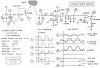
1) I used a much faster opamp that still works at the very low supply voltage of 5V, and its inputs still work at ground. Its power supply current will be a few mA.
2) I made the 1st one non-inverting with a high input impedance and a gain of 101.
3) I added a bit of hysteresis to the output opamp so it doesn't oscillate at its threshold voltage.
Try it, you'll like it. :lol:
This site uses cookies to help personalise content, tailor your experience and to keep you logged in if you register.
By continuing to use this site, you are consenting to our use of cookies.

")