Continue to Site

Welcome to our site!

Electro Tech is an online community (with over 170,000 members) who enjoy talking about and building electronic circuits, projects and gadgets. To participate you need to register. Registration is free. Click here to register now.

  • Welcome to our site! Electro Tech is an online community (with over 170,000 members) who enjoy talking about and building electronic circuits, projects and gadgets. To participate you need to register. Registration is free. Click here to register now.

How to incease a simple 555 timer output

Status
Not open for further replies.

stuhagen

Member
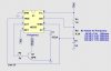
I am making a car tach calibrating device so you can accurately re-install the needles to there correct location. But the Tach uses probably close to 1 amp to run. The typical 555 doesnt support this amount of current output. I tried a TIP31 and it did not work. I have a few NPNs and Mosfets laying around, but before I just start to throw them in to test, I thought I would ask if anyone has a simpler solution. This circuit is a square wave design, The amplitude is the cars voltage, approx 13v. The frequency change is what is realtive to the rpms. I have written in the below schematic the referances to this. I also added a simple NPN with a 1K to base resistor. But testing gives no output. I have read that some Darlington arrays may work. I have also read the appropriate term for this NPN is called "COMPLEMENTARY SILICON POWER TRANSISTORS". But before I go out and buy something on a hunch, maybe I can get the right answer here.

Stu
 

Attachments

  • LTSpice Circuit.jpg
    LTSpice Circuit.jpg
    103.4 KB · Views: 337
What kind of tach requires 1A? All the ones I have seen have high-input impedance (>10K inputs).

Your proposed circuit is set up to sink current. Where does the current come from? What is the open-circuit voltage?
 
Last edited:
What kind of tach requires 1A? All the ones I have seen have high-input impedance (>10K inputs).

Your proposed circuit is set up to sink current. Where does the current come from? What is the open-circuit voltage?

Well, I have *heard* from others that this method works. I have put a scope on my car and made HZ chart based on the the car. 20rpms=1HZ. The tach gets 13v applied to it and the pulse signal comes from the Ignitor to the 3rd input of the tach. Which is a spark based pulse (modulated) This 555 has been set up on my scope to output the correct freq to accurately similate exact rpms. I was *told* that the tach requires more current to drive its coils that the 200ma that the 555 outputs. Hence why I ask the question.

Now I am only *assuming* I am heading in the right direction. If I am not, I am all ears~!

Stu

PS My tach reads 34K from gound to it's input. So I may try hooking it up just to see if the 555 actually moves the needle.
 
A 555 timer is not very accurate as temperature changes so does the frequency of the 555 timer. Connecting a battery to a 555 times makes it warm up so the frequency changes just from being used.

Look at page 171 to 184 of TTL Cookbook. The circuit you want is on page 183.
 
Regardless of timer accuracy you forgot a very important detail in your design. The transistor must have a load (1 to 1.5KΩ) connected between collector and +13V.

Then you'll get an output signal at the collector changing between +0.6 and +13V.

The signal will be inverted!

Boncuk
 
Last edited:
Regardless of timer accuracy you forgot a very important detail in your design. The transistor must have a load (1 to 1.5KΩ) connected between collector and +13V.

Then you'll get an output signal at the collector changing between +0.6 and +13V.

The signal will be inverted!

Boncuk

Thanks...That is really what I was missing. Is this called the "pull-up" resistor? Maybe that is why I was unable to see the pass through signal with my scope. I had my scope probe connected directly to the collector w/o the resistor. Would I take the "ouput" signal on the "collector" side or the 13V side? I assume the collector side. Also I did not have the collector hooked up to the tach input, so there was no load there. I will try to use a 1K resistor in there, then attach it to the tach and see if i get the signal.

Just to clarify what I am doing. I am only trying to make an "association" to where the needle is based on my 555 frequency output to the tach. I will "mark" where the needle rests. Take the needle off, replace the gauge facing, attach the Freq to the tach, then put the needle back exactly where the referance was. so the duration of this whole process is just minutes. I am not using this for any prolong periods of time where there could be heat loss issues. Just to re-calibrate the needles for taking them off and back on.

Stu
 
Hi ya

It might be irrerelevant but all the electronic Tachs I have had anything to do with have had trim pots to fine tune the needle position.
 
Hi ya

It might be irrerelevant but all the electronic Tachs I have had anything to do with have had trim pots to fine tune the needle position.


I agree, there usually is one, but not in my case. As it turns out, the 555 can deflect the needles without the need for a NPN driver. I heard the tach might require more power, but it doesnt. Works fine just running the output pin 3 direct. All I needed is a referance point for replacing the neddle.

Stu

Stu
 
Hi stu,

in case you need more current here are two methods for 1.5A.

Boncuk
 

Attachments

  • TACHO.gif
    TACHO.gif
    13.8 KB · Views: 195
To set the pointer you need your reference signal look to see how far out it is (one or two incriments) take the power off and replace the pointer(lightly at first) and check that your adjustment has worked. When the pointer is right then push it on firmly. Two things to be creful of are
1. The pointer is very flimsy so only manipulate it at the boss.
2. Any colouring on the pointer will be water based. So if you get finger prints on it you will not be able to remove them without taking off the colour.

I have in the past made that very mistake and had to repaint the pionter with acrylic paint. Looks a bit dodgey and guarenteed not to match the other pointers.
 
Status
Not open for further replies.

New Articles From Microcontroller Tips

Back
Top