fouadalnoor
Member
Hey guys,
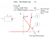
I know this is pretty simple, but I just can't get the full intuition for it. If you look at the attached picture, my lecturer simply drew the load line going from Vb/R to Vb.
I kinda understand how he did it (he is simply drawing the VI characteristic of the resistor) but I want to get it in the maths as well.
Can one of you guys show me the math's steps one at a time so I know exactly how he did it (he got a straight line equation of the form y=-mx+c)