Electro Tech is an online community (with over 170,000 members) who enjoy talking about and building electronic circuits, projects and gadgets. To participate you need to register. Registration is free. Click here to register now.
Welcome to our site! Electro Tech is an online community (with over 170,000 members) who enjoy talking about and building electronic circuits, projects and gadgets. To participate you need to register. Registration is free. Click here to register now.
Exactly what the previous poster suggested. Now draw a circuit diagram of what he said and write the code for a sub-routine to detect the AC. You can either "poll" the input or have the "HIGH" send the micro to the ISR. (interrupt the operation of your program and deal with the HIGH).
Use the same coat-hanger this time. Just connect it to the input of a micro with a voltage-divider and you have the answer. Use a capacitor if you want isolation.
You don't need anything so complex. Just 4 x 1Meg resistors (2 x 1M in series) on each line. 100n caps on each line (200v rating or higher) feeding into the input of the micro. The current will be so low that the protection diodes will clip the signal.
Well, 6 components is a little piece of mind, then that is one less thing to go wrong.
Or, you know use the coat hanger thing, it doesn't matter to me.
The previous circuit (the attached file above) did not provide isolation from both lines so it would need more components. You cannot assume one line will be neutral. You must treat both lines as "active" and provide isolation in the form of "current isolation."
The previous circuit (the attached file above) did not provide isolation from both lines so it would need more components. You cannot assume one line will be neutral. You must treat both lines as "active" and provide isolation in the form of "current isolation."
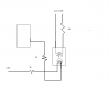
Line isolation and no high wattage dropping resistors or HV capacitors. The lamp represents the AC load. The diodes need to be rated for the AC load current, so may not be convenient in all cases. Also it indicates the load is drawing current, not just that the switch is closed. (i.e. burned out lamp )
It certainly DOES MATTER which way you hook it up. Connect the lower line on the diagram to the "active" wire of an AC outlet and you are directly connected to 120v or 240v.
That's why you should not give advice unless you have actually tested what you provide.
just to put a little light on it here some thing to think about you can use a Optocouplers for isolation and resistor for current limiting. and feed it 120 volts
now we can't look inside a Optocoupler so I just use a led so you can see that
it's not going to hurt your Optocoupler.
I think you'll find the the reverse breakdown voltage of the LED in the optoisolator is something less that 120v x 1.414. Placing a 1N4003 across the LED, and opposite the LED polarity will solve that problem. The resistor will have to be a 2W...dissipating 1.44 W.
I think it a little less then 1.44 W. more like 422.5 Milliwatts but any way I let it stay on for a hour with just a half watter 10 k and it didn't get hot You no phone's have them Optocouplers in them to pickup the ring-signal AC wave it can be up too 90 volts
This site uses cookies to help personalise content, tailor your experience and to keep you logged in if you register.
By continuing to use this site, you are consenting to our use of cookies.

") )
)