Continue to Site

Welcome to our site!

Electro Tech is an online community (with over 170,000 members) who enjoy talking about and building electronic circuits, projects and gadgets. To participate you need to register. Registration is free. Click here to register now.

  • Welcome to our site! Electro Tech is an online community (with over 170,000 members) who enjoy talking about and building electronic circuits, projects and gadgets. To participate you need to register. Registration is free. Click here to register now.

How to debug this sound COB circuit?

Status
Not open for further replies.

alaasalama

New Member
Hi guys!
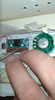
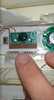
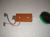
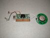
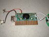
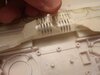
So, my kid has this "Animals Sounds Book" which is broken and doesn't produce any sound now, although the batteries are good.

I've attached two images showing the COB circuit, but I'm beginner and I don't know how to trigger these metal strips to test the output?

Also, any general idea about how to debug this board would be appreciated, wiring diagrams or what to search for?
 

Attachments

  • circuit2.png
    circuit2.png
    788.1 KB · Views: 215
  • circuit.png
    circuit.png
    816.3 KB · Views: 215
You should be able to simulate whatever contacts there are in the book by using a bit of wire with bared ends and linking either the left end contact or the right end contact to one of the eight in the centre.

And you could try linking the left half of the eight in the middle to the right, in all combinations.

You can very gently use a pencil eraser to clean both sets of contacts, or just put a strip of plain paper between the two parts, press gently and pull the paper out. That is a good way of removing tarnish and contamination from plated contacts, without damaging the surface to much.

Unfortunately, the chances of finding any technical info on a COB module like that is next to zero, and nothing can be done to repair it if the external circuitry is OK.
You cannot remove the encapsulating resin without also destroying the hair-fine links embedded in that which connect the IC die to the PCB tracks..
 
Thanks for your reply!

I created this video trying to do what you have mentioned (excuse me if I did something wrong, I'm literally playing here):

I would appreciate if you have any insights/feedback.

Also, I've attached some extra images and I feel I need to mention the book was working fine, then some buttons were working and others not, then the voice was cracking, not clear, then no sound at all.
 

Attachments

  • book_4.jpeg
    book_4.jpeg
    98.8 KB · Views: 192
  • book_3.jpeg
    book_3.jpeg
    126.6 KB · Views: 198
  • book_2.jpeg
    book_2.jpeg
    122.9 KB · Views: 192
  • book_1.jpeg
    book_1.jpeg
    62.7 KB · Views: 189
in the first picture, you have a red wire (i assume it's from the battery because it goes to the power switch) and the red wire looks like it got pinched in one of the screw standoffs for the cover.... make sure that wire has continuity between the battery and the PCB...
 
Have you tested the switch to see if its still working? The video kind of seems like you have no gnd/vss, which looks like its controlled by the switch and connected when its set to "ON".
 
Status
Not open for further replies.

Latest threads

New Articles From Microcontroller Tips

Back
Top