Electro Tech is an online community (with over 170,000 members) who enjoy talking about and building electronic circuits, projects and gadgets. To participate you need to register. Registration is free. Click here to register now.
Welcome to our site! Electro Tech is an online community (with over 170,000 members) who enjoy talking about and building electronic circuits, projects and gadgets. To participate you need to register. Registration is free. Click here to register now.
Am I able to create a 60Hz output from a common 32KHz oscillaltor? As far as I can see, the closest I get is 64Hz something that wouldn't be accurate enough for a digital clock.
Those "32KHz" oscillators are really 32.768KHz or 32,768 Hz which will divide down by twos to exactly 1 Hz or 1 pps, perfect for they typical clock application. If you need 60 Hz (I assume for a clock chip that requires 60 Hz from the power line), you need to start with a different frequency. Multiply 60 up by twos until you get something you can find and work with. But if you have the power line available, why not use it for your clock? The long-term accuracy of the power line is excellent (although the short term stability can suck, so it's lousy for frequency counters beyond 4 or 5 digits) which is why the old mootor-dirven clocks were always on-time.
No, I need the 60Hz signal to make the milliseconds, or those numbers that are smaller than seconds, I really don't know the name :? And I can't use the powerline since the whole circuit is battery powered and cordless. Any suggestion?
Since you cant divide to 60Hz exactly, you will have to take care of the error in software. Simply write a routine that keeps track of the pulses you are off by and when they total a division that you can use, add it to your time. Accuracy at any given 1/10 of a second wont be 100% but it will be close enough!
-Bill
P.S. The clock on your computer runs by a similar method. The clock outputs 18.2 pulses per second (IIRC) which does not work out to an even time interval so software takes care of the error.
You can also get from 32768 Hz to 60 Hz with a PLL, but I may be opening a can of worms for myself by mentioning it. I like the software "PLL" better, if it solves lac's problem.
hmm... I have never been into writing software for a microcontroller, as I assume you mean by your method? But I'll be happy to learn! Feed me some links or something, please.
hmm... I have never been into writing software for a microcontroller, as I assume you mean by your method? But I'll be happy to learn! Feed me some links or something, please.
Thanks! Should be able to put this to work. Any sites with info on this setup? What are those caps and the resistor for? How do I know their values? And one last question, how accurate will this hardware solution be?
You need the 74HC4046 datasheet. I'll warn you, this is not simple if you have no experience with PLLs.
The resistor and caps are the loop filter. They are for loop stability, and they must be selected according to equations in the datasheet.
The output frequency will be exactly Fin*15/8192. If Fin=32768 exactly, then Fout=60.00...0 Hz. If Fin is high by 0.1%, then Fout will be 60.06 Hz. I think you get the idea. Here is a site with useful information. Here is an app note from ON Semiconductor.
If you're needing your times in multiples of 10 (i.e., 1s, 100ms, 10ms, 1ms, 100µs, etc.), an option other than the PLL trick is to begin with a 1 MHz oscillator (you can get them as 4- or 5-pin DIP packages) and divide down using CMOS decade dividers. As I recall, there's a multiple-decade Johnson counter available in 4000-series CMOS. Battery drain will be nil.
If you're needing your times in multiples of 10 (i.e., 1s, 100ms, 10ms, 1ms, 100µs, etc.), an option other than the PLL trick is to begin with a 1 MHz oscillator (you can get them as 4- or 5-pin DIP packages) and divide down using CMOS decade dividers. As I recall, there's a multiple-decade Johnson counter available in 4000-series CMOS. Battery drain will be nil.
Definitely a much better way to go. I got caught up in the design challenge (if you can call it that), plus I thought that maybe he really wants 60ths of a second (but why?).
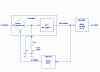
Here is a circuit I built sometime ago. It uses a easy to get crystal of
2.4576Mhz, and a CD4060. The 4060 divides the crystal by 8192 to get 300 Hz. The CD4017 divides by 5 to get 60 Hz. The first CD4018 divides by 6 and the second one divides by 10. If you only need 60 Hz don't use the 4018's.
Ahh. Thanks for input! But can't I use decade counters (7490) instead of the 4060s? Cause I've got a lot of them laying around. And I need the 60Hz output for the milliseconds, as already stated.
Ahh. Thanks for input! But can't I use decade counters (7490) instead of the 4060s? Cause I've got a lot of them laying around. And I need the 60Hz output for the milliseconds, as already stated.
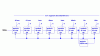
The input is 60Hz and will be divided by 10 and 6 four times, the output from each of the deacde counters will be sent to a BCD encoder, wich will show the number, or "time" at a 7-seg. Got it now?
------
DC=Decade Counter
Source -> 60hz ->
DC div.10 -> 00.00.00.00
DC div.6 -> 00.00.00.00
DC div.10 -> 00.00.00.00
DC div.6 -> 00.00.00.00
DC div.10 -> 00.00.00.00
DC div.6 -> 00.00.00.00
DC div.10 -> 00.00.00.00
DC div.6 -> 00.00.00.00
the numbers in red, are the numbers that are being sent to the 7-seg. The first pair is hours, the next is minutes, the next is seconds and the last is milliseconds (milliseconds, is it the right name?)
hmm.. After looking at "k7elp60"'s ciruit. I wonder if I'm able to switch the 4060 for two 4040 chips to get 300Hz, and then switch the 4017 for a 4090, and get 60Hz? The reason for this is that I have those chips in my box already.
If you want to read hundredths and tenths of seconds, you need a 100Hz timebase, not 60Hz. Below is a block diagram of my understanding of what you want.
Are you planning on stopping the clock, i.e., using it as a stopwatch? Otherwise, there is no way I can see that the 2 least significant digits will be useful. They change too rapidly for the eye to track them.
This site uses cookies to help personalise content, tailor your experience and to keep you logged in if you register.
By continuing to use this site, you are consenting to our use of cookies.