Heidi
Member
Dear friends,
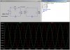
I would like to construct a transformer circuit in PSpice, but the transformer's winding is a little different than usual, as shown in the figure below. Can you please give me some hints of how to do it? There seems no way to specify the dot placement in the XFRM_LINEAR part.
Thank you!
I would like to construct a transformer circuit in PSpice, but the transformer's winding is a little different than usual, as shown in the figure below. Can you please give me some hints of how to do it? There seems no way to specify the dot placement in the XFRM_LINEAR part.
Thank you!