Continue to Site

Welcome to our site!

Electro Tech is an online community (with over 170,000 members) who enjoy talking about and building electronic circuits, projects and gadgets. To participate you need to register. Registration is free. Click here to register now.

  • Welcome to our site! Electro Tech is an online community (with over 170,000 members) who enjoy talking about and building electronic circuits, projects and gadgets. To participate you need to register. Registration is free. Click here to register now.

How to charge a supercapacitor FAST?

Status
Not open for further replies.

lxlxlx

New Member
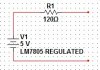
I need to charge two 2.7V, 1F supercapacitors in series from a LM7805 regulated voltage source connected in series with a 120 ohm resistor. See attachment for the circuit. I know I can just connect the supercapacitors directly to the voltage source, but is there any faster way to charge the caps?
 

Attachments

  • 123.jpg
    123.jpg
    16.5 KB · Views: 403
It takes an infinite current to charge a capacitor in zero time...

With a 5V source, charging 0.5F through 120Ω takes ~3RC = 180 sec = 3 min. The peak current is only 42mA.

If you take out the resistor, the LM7805 goes into current limiting (~1.9A), so that shortens the charging time to t=C*ΔV/I = 0.5*5/1.9 = 1.3 sec. Depending on the input voltage, the 7805 is dissipating >14W, so it better be on a big heatsink.
 
Last edited:
The circuit (LM7805 and resistor) cannot be changed. Is it possible to use some active components to make it charge faster? Like using a switching regulator to boost to a higher voltage? or build a current source?
 
What about using a GE C5 SCR from the battery to the cap? The C5 is rated at 5 amps and as long as this is intermittent duty, it is able to take a much larger load. If in doubt, add a small series resister in the cathode lead on the order of a quarter of an ohm. The C5 has a very sensitive gate and will even fire with 0 or even a small negative bias depending upon the individual unit. Last, the load has to be off while charging so the SCR will starve out before going to normal operating mode.
 
What is the primary power source (if not the 7805)?

Can you add circuitry that externally parallels the existing 7805-120Ω (You didn't make this clear)?
 
No. You can't add stuff in parallel. Only the two contact points on the right side of the circuit are accessible
 
No. You can't add stuff in parallel. Only the two contact points on the right side of the circuit are accessible

Huh??? Your circuit shows a 5V source and a resistor, not the super capacitor, which is presumably what the circuit connects to???? Why cant you connect to the super capacitor which is not even shown in your drawing????
 
I mean you can do whatever you want across the two terminals but you can't change the 7805 and the resistor. Think of the circuit as a power source. Sorry for the confusion.
 
Is this an MPPT type schoolwork exercise?

Are you looking for some sort of adaptive SMPS that goes between the circuit you posted and the supercapacitor?
 
It's a design project we're working on. Yeah, i think it should be something like a SMPS between the circuit and capacitor. But how do we do it?
 
Read this for starters

Hint: If you were going to connect a resistor to your circuit, what resistor value would result in maximum power transfer to that resistor?
 
it should be 120 ohms as well. same as the internal resistance

Bingo! So you should build an SMPS that always presents an input impedance of 120 Ohms.
 
ok..so do you think the SMPS will make the charging faster than directly connect the supercaps to the source?
 
I dunno. If I wanted to find out, I would write some equations...

However, intuitively, if you think about what is happening with the RC charging curve, there is only one instant in time as the capacitor charges when the product of voltage*current matches the maximum power transfer point. If you could keep the source loaded such that the downstream load is always at 2.5V/20.833mA = 120Ω for the entire time the capacitor is charging, then it seems it would happen faster than the simplistic case.

To try this out, I did this simple sim.

First circuit is the brute force RC charge-up. Note that the dark blue trace is the voltage vs time of C1 and the red trace is the power extracted from the source. Note that the peak power happens as you would expect when C1 is at 2.5V, and the peak power is ~52mW.

Second circuit charges C2 with a magic behavioral current source which automatically adjusts its current so that it's power output is a constant 52mW. The green trace is the voltage at C2, and the light blue trace is the power output of B1 (i.e. constant at 52mW).
Note that the charging curve of C2 is always ahead of C1. Not a huge win, but the second circuit always wins, especially if you insist on charging C1 all the way to 5.000V :D

Now, all you have to do is figure out how to build B1....
 

Attachments

  • DF155.png
    DF155.png
    45.1 KB · Views: 364
Last edited:
(Reply to lxlxlx) Those caps have a high internal resistance and they are very difficult to charge fast. You can force the cap voltage to full instantly but they will still take quite a few seconds (10 or more) to become fully charged.

It is also very likely that they will be damaged and/or have a reduced life if you try to repeatedly fast charge them.

To MikeMl, nice idea of the constant power cap charger. I'm not sure what the benefit is of constant power over constant current, but here is a constant power boost SMPS. It regulates based on input current, and as input voltage is fixed (5v) the input power is fixed.

I think it meets your case of a constant power SMPS to charge up a cap.

**broken link removed**
 
Last edited:
Mr RB said:
...To MikeMl, nice idea of the constant power cap charger. I'm not sure what the benefit is of constant power over constant current, but here is a constant power boost SMPS. It regulates based on input current, and as input voltage is fixed (5v) the input power is fixed...

Roman, the goal of the exercise is to charge the capacitor not from a constant 5V, but from the power that can be drawn from 5V with a source resistance of 120Ω. That means that the switcher input can only get 2.5V at 20.833mA. As I showed above, the switcher must operate at a constant power input of 52mW. You could also servo the switcher to operate such that it maintains a constant 2.5V at it's own input...
 
Last edited:
It does operate at a constant input power. As far as "power that can be drawn from 5V with a source resistance of 120Ω" sorry I missed that part, thinking it was more that 120 ohms was the max load allowed from the 5v source, so 5v at 42mA was ok.

If the source is exactly as depicted and you want to run the SMPS from 2.5v at 21mA then just change the current set resistor in my circuit from 6.8 ohm to about 15 ohms, so it will draw a constant input current of about 21mA average.

You asked "how do we build B1" and I just posted a working example of a constant input current SMPS converter that had been built and tested. It acts as a "constant input power SMPS" from his source, as you asked. I'm not saying it will work well from 2.5v input but it was posted as a very simple example of the concept you asked for. :)
 
To MikeMl, I know how to build a current mirror with two BJTs but how do you make a behavioral current source (B1 in your figure)?

To Mr RB, i saw that the circuit has a 13V output. is that too high for charging two 2.7V caps in series? How to make the output voltage lower?
 
Hi lxlxlx, that circuit is not an ideal example of a circuit for your application, it just shows the principle Mike was discussing, ie a switchmode converter with constant input current/power.

Do you seriously want a circuit to run from 2.5v 21mA and charge a cap to 5.4v? How much complexity? How efficient? And what is the voltage source and why those exact limitations on the input source? What is the whole lot going to do?
 
Last edited:
Status
Not open for further replies.

Latest threads

New Articles From Microcontroller Tips

Back
Top