Continue to Site

Welcome to our site!

Electro Tech is an online community (with over 170,000 members) who enjoy talking about and building electronic circuits, projects and gadgets. To participate you need to register. Registration is free. Click here to register now.

  • Welcome to our site! Electro Tech is an online community (with over 170,000 members) who enjoy talking about and building electronic circuits, projects and gadgets. To participate you need to register. Registration is free. Click here to register now.

How to build my electronic project better

Status
Not open for further replies.
Hello,

I regularly make some small projects, mostly for me, sometimes for my friends. They include some simple components, like ESP8266, some step-downs/step-ups, some relays, some voltage led displays, etc. Nothing fancy.

I attached an example of 1 of my projects. Now the problem i am having is, it is really hard to replace a single element if it goes bad. Imagine replacing the little step-down, i would need my equipment if i was to replace it at my friends place.

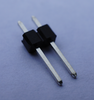
I am looking for a better way to design and make my little projects. It would be great if all my components, including ESP8266 could be simply swapped with a working part, using the little leg elements (in a similar way that you can replace a fan in a computer, simply unplug it, plug a different one in). Also all those wires are dead weight, it would be a lot easier if i had like a circuit board with all those connection and i would only solver the elements to the appropriate location. But i am wondering how much would a custom circuit board cost - would it make sense, since all other components you see are very cheap (probably everything on the image combined is around 10$ .. )

I am just starting with electronic projects and would be really glad for some advices.

20200907_203655.jpg
 
Circuit boards of up 100mm × 100mm can be fabricated by a number of fab houses in China for a cost of $5 for 10 circuit boards. It's very practical to lay out a sort of mother board to plug modules like a NodeMCU, relay board and others into.

You'll need schematic capture/pcb layout software to design a circuit board. JLCPCB.com is one of the good PCB fab houses, and they also offer EasyEDA software to lay out circuit boards. It's a very good and easy program to learn. It makes ordering boards from JLC simple, but can also provide Gerber files so you can have boards made anywhere you want.
 
Here's an example of a "mother board" I designed for a collection of electronic modules. It was for a product development effort to make some prototypes at low cost. The modules were cheaper than the cost of components to build them, and this approach allowed for easy assembly by somebody with limited soldering skills.

Screenshot_20210311-181606_Edge.jpg
 
Thank you for all your replies.

I decided im gonna do this. First, use stripboard that has holes throughout it. This way i can solder pins directly to the board and make my elements "plug and play", so i can swap any element if its broken. Also its easy to solder a few pins neighbouring pins together. I have to decide if i will use wires on the front or back side of the board.

I also checked custom PCBs and i decided i will also use them but only when/if i need to make like 5 or more of the same setup. To only make 1, i dont think its worth the work. Still, might be fun. I remember that in highschool, we did this in 1 of the classes. Sadly, it is many many many years ago so i dont remember much, but it was fun.
 
I figured most things, how to do it. 1 of the things that is still a problem is this small step-down i use in mostly any project. I would like it to be swappable without any soldering or wires. So my plan was to solder pins to step-down, 1 pin to each of the holes (pins fit into the holes nicely, the step down is the size of hand nail). Its easy to separate those pins on the bottom right picture so i get a single pin. But now i also need a female header that will be on the PCB itself. And here is the problem. I cant seem to find a single female header, the lowest i can find is 2 pin. When i look for single female header all i get is female dupont. But thats not what i need. I need exactly what u see on the middle image, but only a single one. That way it will be swappable, but without dupont wires, which tend to get unplugged

Mini-360-4.jpg51AIJP1GQmL._SL1000_.jpg s-l300.png
 
Are you making a pcb "mother board"? If so, I would lay it out for 2 pin female headers, and connect them in parallel or leave the extra pin unconnected. Header pins are square, so you need 2 pins to keep the connector aligned. I'd solder the female 2-pin sections to the mother board, put single pins where they are needed, then position the module on those pins and solder them in place so the alignment is correct.
 
A better but slightly more complicated option would be to design the motherboard to fit Mill-Max sockets for round pins, and use headers with round pins on your modules. Then there is no worry about keeping a square pin aligned with a square hole. They have many options for pcb sockets.

mill-max.jpg
 
The middle picture was just an example. I am using headers that have same sides - doesn't matter how you connect them. I am adding another picture to make things clear. As for what i am doing, i included a picture of what im trying to do - but do it smarter, with less wires. Because those wires are just waiting to get unplugged.
 

Attachments

  • ne-row-two-way-male-header-2_54mm.png
    ne-row-two-way-male-header-2_54mm.png
    354.9 KB · Views: 192
The picture is and was perfectly clear. As I said, the posts are square. The fit into a socket designed for a square post.

If the pin and socket aren't aligned properly, the socket will not make proper contact with the post.

A pin oriented like this: <>

will not mate properly with a socket oriented thusly: □

Sorry the world won't conform to your vision.
 
Ah, i understand what u mean now. But it wont be hard to align those pins since they have a plastic square on them, im pretty sure i can get that square enough. But good call, will test asap and see if its doable or i will have to go the round pins way
 

Attachments

  • ne-row-two-way-male-header-2_54mm.png
    ne-row-two-way-male-header-2_54mm.png
    354.9 KB · Views: 186
The contact in a female header is a thin metal fork as shown in the drawing below. It contacts a square post over a small contact area on opposite sides if the post is inserted squarely. If the post is rotated even a small amount, the already small contact area will be greatly reduced. The result will be an unreliable connection. That's the reason you can't buy a single position male or female header.

Dupont connectors are a different game. There, you have a square (pin or socket) on the end of a flexible wire plugging into a square (socket or pin) header on a circuit board. The pin and socket align because (at least) one of them is free to rotate into proper alignment.

header section.jpg
 
lol, i thought it was 100 something, now a days i just google "arduino headers"
also single headers are a bad idea, they slip around way too much
i buy 16 pin strips, then when i need x amount i just cut it down, at the cost of a pin or 2
 
Those stripboard are awesome. I already used a couple of them. The only thing i kind of have a problem with is ... i often have to connect many pins together. First i tried only using solder and that was nuts - i used so much solder that i will actualy save the board when i no longer use it to recycle the solder. Its insane. Then i just used a thin wire and ran it along the pins and soldered to each one - that was easy and didnt use much solder, but i got a little nervous about a split wire that i wont be able to see that will make a contact somewhere. I also found boards that have connected pins together kindof like breadboard but that is just not ok cause that will be to much work to break contacts and make sure there isnt some short circuit. So how are you guys connecting different pins together ?
 
I use various techniques, depending what I'm building, how critical it is for speed & grounding, if it's a prototype that will probably be scrapped (or cannibalised) or something that must last.

A few examples I have to hand in the photo below:

Bottom left, a little test rig voltage regulator for 5V & 3.3V built on single sided stripboard.
Tracks are cut with a small drill bit spun by hand, or an old Vero cutter.

I usually use a solder blob to bridge adjacent tracks, or leave component leads long and bend them to suit before soldering.

Lower centre, a bit of ground plane square pad board with signal connections made using bits of wire wrap wire. That strips easily and the insulation does not shrink back while you are soldering.

Lower right, ground plane stripboard, the same soldered wire wrap wire for interconnections.

Top centre is a prototype of a rack computer I/O card, built on a Vero ground plane IC pattern board - quite possibly the style that plug-in protoboards copied, as I'm pretty sure they came out rather later.

I still use wire wrap for complex logic prototypes and one-offs, as it's a lot easier to get high density packing that if you need space to solder wires at the side of every IC pin.

Prototypes.jpg
 
This wire wrap thing seems kind of tedious. Is it better than simply using the wire, put it through the hole and solder in ?
I was even thinking of using simply dupont cables and solder the ends. Though it pains me to keep buying those dupont cables while i have 10s and 10s of meters of wire pieces remains in my workshop. Though it does take more time to strip the insulation down and the insulation tends to melt which is kind of not safe when using adjacent pins like this. Eh, i just ordered some jumper wires for breadboard, actualy a few types and i will see how it goes. As much as i would love to use my old wires to save money and feel good about myself ... far to often i dont count the time it takes for something like this ... and how much money i would earn in this time doing my other work :)

Thank you for all the advices, keep them coming :)

I have a few more questions for things i would need:

1) something like relay but smaller, cheaper and for lower currents. Transistor ?
2) i made a simple gadget to check if soil is dry or moist. Its 2 iron sticks, connected with led and a battery. You stick it into soil and if its moist - the led will light up. But .. that is not useful to have in the soil all the time since battery will run out. So i was thinking ... would it be possible to make something that would only light the led when there is no connection between iron sticks. Sort of like an element that negates. A relay could do that but relay uses even more energy than a led. It would have to be something that could run for months on a single AA battery.
 
The OPTOMOS relay is pretty cool. It needs ~1mA to light the internal LED.

#2, You have to use an AC voltage, otherwise plating occurs. There are magnetic latching relays that only require a pulse to set the state, They retain their state forever.
 
This wire wrap thing seems kind of tedious. Is it better than simply using the wire, put it through the hole and solder in ?
Wire wrapping, using sockets etc. designed for it with the correct size long pins, is very quick - probably about five seconds or so a joint, from starting to strip the wire to it finished.

Strip the wire, put the end in a wire wrap tool, spin it on. Instant high reliability, low resistance joint with a built-in strain relief!
And just as easy to remove, using the correct tool, with no mess.

This is a close up view of a joint, and the end of the tool that made it. They do not look much & don't take any effort, you can just spin the hand tool between your fingers - but due to the way the wire is pulled sideways out of the groove in the tool bit as it is turned, and the bending force around each corner of the square pin, the point contact pressure at each corner of each wire turn is in excess of 50,000psi !!

Wire-Wrap_Joint.jpg

Some of my collection of wire wrap tools; you only actually need the small blue hand tool at the top - that has wrap and unwrap at the ends plus a wire stripper in the centre.
The others are convenience (the cut & strip tool) or just to save your fingers when doing hundreds of joints.

Wire-Wrap_Tools.jpg

Having said all that, for most small boards and prototyping I just use soldered wire wrap wire for the connections, no wire wrapping. I have vast quantities of the wire and it's far easier to work with than normal PVC insulated wire, for things that do not need thicker connections.
 
I worked on a commercial product that used WW boards. One day, after many years operating, the operator could not see a number, because a color went out on the display, I have no idea how I found it, but I did have schematics. Power and ground were soldered and the other connections wire-wrapped. They missed soldering ground or +5 on an IC.

I think some early Cray supercomputers were wire-wrapped and the lengths of the wire mattered.
 
Status
Not open for further replies.

Latest threads

New Articles From Microcontroller Tips

Back
Top