Continue to Site

Welcome to our site!

Electro Tech is an online community (with over 170,000 members) who enjoy talking about and building electronic circuits, projects and gadgets. To participate you need to register. Registration is free. Click here to register now.

  • Welcome to our site! Electro Tech is an online community (with over 170,000 members) who enjoy talking about and building electronic circuits, projects and gadgets. To participate you need to register. Registration is free. Click here to register now.

How to Avoid the Resistor Divider Leakage?

Status
Not open for further replies.

cooperhow

New Member
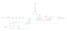
I want to use 1kV to provide 10mA 20V, for which I would use a resistor voltage divider network.

However, there is a continuous leakage to ground in parallel. Is there a way to fix this leakage but still provide 20V to my system? That leakage would take 2 times more power handling on the resistors.

Doubtlessly, I would use a LDO to keep the 20V stable. I did not provide many details because I thought there could be a way exclusively to avoid leakage in a voltage divider.

Greatly appreciate any ideas!
 
"Yee canna change the laws of physics Jim" - the whole idea sounds ludicrous, EXACTLY what are you trying to do?.

Incidentally, you would have to get rid of about 50W of heat doing it with a voltage divider (based on the standard ratio of 5 to 1 for voltage dividers).
 
So, you're using a 1000V supply and want to use a voltage divider to produce 20V at 10mA? So you need the total resistance to be (double required amps = 1000/0.020=50k total resistance) A 1000 to 20 V relationship is 1:50 so go with a 1K resistor with 20V across it and 49K with the rest.

BTW, had too much beer and wine to even contemplate that being correct. Check all computations.

Mike.
 
I was under the understanding that resistors, common resistors, were only good up to around 200V. There are I'm told high voltage resistors but not that common.
 
I would use a 20 volt Zener diode, to limit the voltage. If the load goes away the output voltage could get to 1kV unless there is a way to limit the voltage.
1667489363165.png
 
I was under the understanding that resistors, common resistors, were only good up to around 200V. There are I'm told high voltage resistors but not that common.
The voltage rating is given in the specifications - but 'generally' the higher the wattage, the greater the voltage rating. You can get special high voltage ones (if you can find them?), but it's common to use series resistors to increase the overall voltage rating.
I would use a 20 volt Zener diode, to limit the voltage. If the load goes away the output voltage could get to 1kV unless there is a way to limit the voltage.
Which was why he specified 'voltage divider' :D


Above might help.


Regards, Dana.
 
If I understand you, by leakage, you are referring to the current wasted through the ground-connected resistor in the divider. If you use a 1000V linear regulator, you can reduce this current while providing a larger current to your 20V system. You can implement this regulator using the standard zener + voltage-follower circuit, e.g.
iu
.
Obviously the "12V" rail will be your 1000V, and the "5V" output will be your 20V, etc.

Bare in mind that the transistor will be dissipating ~10W if you are drawing 10mA from the output, and should be on a heatsink. Also be aware that common zener diodes may require a few milliamps to regulate at the specified voltage; there are very low current zener diodes available though, e.g. the following diodes are specified at 50uA: https://www.diodes.com/assets/Datasheets/ds30410.pdf
 
Last edited:
why?

Please define leakage current in parallel.

That was my reaction when I first read this. There may be some systems using 1KV , but for most things it comes from a transformer. If you have a transformer to make the high voltage from a mains voltage, why not use a smaller one for the 20V?
 
I would use a 20 volt Zener diode, to limit the voltage. If the load goes away the output voltage could get to 1kV unless there is a way to limit the voltage.
View attachment 139122
Hi, I was trying to tackle a similar problem today and by chance came across this. I tried using 11.1V 5W zener diode. The problem is the circuit I am trying to power is made so if input voltage is higher than 60V it should open a optocoupler and light up a led as warning (I only care about the HV part since LV part is made). It needs to withstand up to 600V or something though since voltage is not constant. But it still needs that galvanic isolation. The guys who tried making it before me tried to power the thing with only a resistor voltage divider and confused when their tiny smd resistor keep burning :/
First idea was using a linear converter that was made for high voltage. But those aren't available in my country so I wanted to see if I can make something similar since comparator and optocoupler uses so little current.
1668876249646.png

Reference voltage for comparator is 3V and it opens when there is like 50V at the battery bank for safety.
If I adjust the zener resistor for something large so that it doesn't burn the resistor it will not work until there is at least like 150V because voltage is too low for comparator to function. If I use lower resistance it will work at lower voltages as it should but burn when it reaches 400V. And if load is disconnected somehow, zener has to suck a lot of current to drop the voltage which it can't so voltage starts to rise above its specification and it starts heating up.
Unfortunately I killed my beloved chonky cool looking high wattage zener diode after accidentally shorting it to 100V or so directly and destroying some resistors in the progress and concluded that that is not suitable since input voltage is varying to much. Probably charging a 4500uF 450V capacitor to test the circuit wasn't the brightest idea since it can destroy stuff in case of shorts as it did and flashbanded me in the process.
I have three options left: Making a linear converter with a high voltage bjt like dougy83 which is something I want to avoid since circuit needs to be small to fit inside the battery box. Or I will use LM317 and make it work with higher voltages by combining it with the bjt linear converter. Or at the worst case scenario we will just buy the linear converter. Want to get your opinion about this. Or I will just feed the comparator a higher voltage like 30V and use a high voltage high power zener diode to cope with it.
 

Attachments

  • 1668876224033.png
    1668876224033.png
    23.6 KB · Views: 155
The parts and text on your schematic are too tiny to see because they are much too far apart. They are also hard to see because there is no contrast.
I fixed part of it and it us the same size as the original:
 

Attachments

  • high voltage.png
    high voltage.png
    40.6 KB · Views: 141
First idea was using a linear converter that was made for high voltage. But those aren't available in my country so I wanted to see if
I have three options left: Making a linear converter with a high voltage bjt like dougy83 which is something I want to avoid since circuit needs to be small to fit inside the battery box.
That circuit I attached is simply a linear regulator; it performs a similar function to your NCP785 IC. The only thing that would be large about that circuit is the heatsink required to dissipate the wasted power; you will have to get rid of a similar amount of power for any linear dropper you come up with (including the two other options you proposed).
 
You can use a TOP series single chip switched mode PSU as a high voltage buck regulator, eg. this is from a Power Integrations data sheet, also linked below.

Ignore the extra 5V regulator for a single output PSU. Remember its non isolated!

TOPSwitch_Buck.png


I've been experimenting with this configuration using the TOP254 - TOP258 series in an 8 pin DIL style package, which are rated up to around 600V input. Those can be wired in the same three pin configuration, with extra pins linked appropriately.

The TOP devices include soft-start and provide their own startup supply. Regulation is not precise with the odd feedback, but fine for most things.
The app note gives an alternate configuration with an optocoupler for feedback, which has higher accuracy.

 
The parts and text on your schematic are too tiny to see because they are much too far apart. They are also hard to see because there is no contrast.
I fixed part of it and it us the same size as the original:
Eagle do be like that. Can't even find a decent Axial Resistor model with changeable resistance value. Sparkfun ones are to short and damage the carbon resistors with thicker leads.
 
That circuit I attached is simply a linear regulator; it performs a similar function to your NCP785 IC. The only thing that would be large about that circuit is the heatsink required to dissipate the wasted power; you will have to get rid of a similar amount of power for any linear dropper you come up with (including the two other options you proposed).
What kind of transistor is best for this type of application. I don't know how to look at catalogs and pick one. Looks like only ones I can buy online with high voltage rating is BU508 even though 8A current rating is way overkill. I will check the collab space, they had some metal case medium power transistors thay may have high voltage rating.
 
Last edited:
Status
Not open for further replies.

Latest threads

New Articles From Microcontroller Tips

Back
Top