Electro Tech is an online community (with over 170,000 members) who enjoy talking about and building electronic circuits, projects and gadgets. To participate you need to register. Registration is free. Click here to register now.
Welcome to our site! Electro Tech is an online community (with over 170,000 members) who enjoy talking about and building electronic circuits, projects and gadgets. To participate you need to register. Registration is free. Click here to register now.
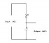
It's a simple potential divider - at different frequencies the effective 'resistance' of the capacitor C will be different, it will decrease with increasing frequency. At the frequency where the impedance (AC resistance) of C equals that of R, the output will be half the input. Where it equals half that of R the output will be 1/3, and so on. It's a fairly crude filter, but it's commonly used - and it only has a very low roll off.
Caps appear as open-circuits to DC voltages, they also look like short-circuits to AC voltages.
You can appreaciate then that AC components will be shorted to GND thus not contributing to the output voltage.
the 3dB freq of the knee point of this filter is:
f = 1/(2*pi*R*C)
As mentioned it is a voltage divider its just the lower component is frequency dependant
For a resistor:
Z = R
For a cap
Z = j/wC - where j is the complex component and w is ang freq
So you can still do the usual maths that you would to work out the voltage of a resistive voltage divider just with j/wC (as long as you know complex maths...)
This site uses cookies to help personalise content, tailor your experience and to keep you logged in if you register.
By continuing to use this site, you are consenting to our use of cookies.