Hi.
please have a look at the attached images i attached here. i need to ask few questions.
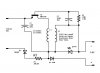
First circuit in question (see image named "charger"). I just need your kind help to understand how it works?
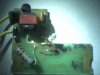
I made the schematic myself so to understand better i also attached the photo of the board( see image named "Charger 1"). Is the output of this circuit isolated from mains voltage?
Second circuit (see image named "Electronic transformer" as said by original image).
There are few things i don't fully understand. L1, L2, L3, should be wound on the same ferrite core? What type of core can be used for these.
L4 & L5, is output transformer should be wound on separate core? what type of core may be fine for it?
Under L4 & L5 the transformer winding turns details there are symbols i am not sure about those. what those two identical symbols means?
Thanks a lot in advance.
please have a look at the attached images i attached here. i need to ask few questions.
First circuit in question (see image named "charger"). I just need your kind help to understand how it works?
I made the schematic myself so to understand better i also attached the photo of the board( see image named "Charger 1"). Is the output of this circuit isolated from mains voltage?
Second circuit (see image named "Electronic transformer" as said by original image).
There are few things i don't fully understand. L1, L2, L3, should be wound on the same ferrite core? What type of core can be used for these.
L4 & L5, is output transformer should be wound on separate core? what type of core may be fine for it?
Under L4 & L5 the transformer winding turns details there are symbols i am not sure about those. what those two identical symbols means?
Thanks a lot in advance.