Continue to Site

Welcome to our site!

Electro Tech is an online community (with over 170,000 members) who enjoy talking about and building electronic circuits, projects and gadgets. To participate you need to register. Registration is free. Click here to register now.

  • Welcome to our site! Electro Tech is an online community (with over 170,000 members) who enjoy talking about and building electronic circuits, projects and gadgets. To participate you need to register. Registration is free. Click here to register now.

How do I make my induction heater get 200 degrees hotter?

Status
Not open for further replies.

gary350

Well-Known Member
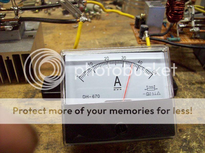
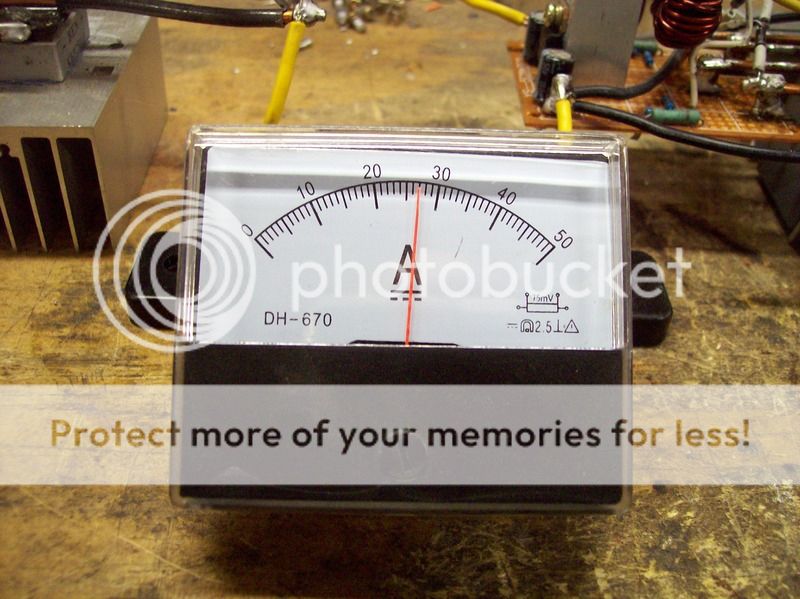
My amp meter arrived now I know for sure how many amps the circuit is. 36 amps with the 3/8" diameter metal rod and 27 amps with the 1/4" metal rod.

21.1 vdc power supply with no load.
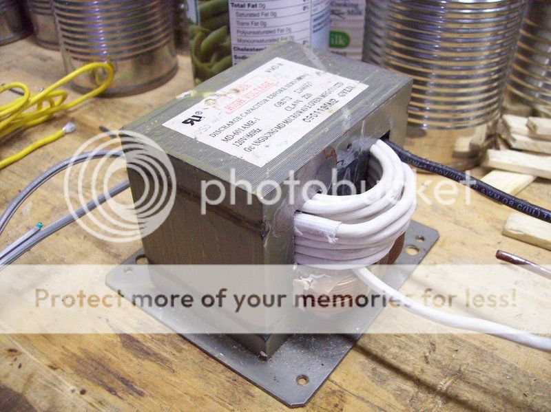
17.53 vdc at 6 amps no load in coil. 105 watts
13.7 vdc at 27 amps with 1/4" load. 369.9 watts
13.1 vdc at 36 amps with 3/8" load. 471.6 watts

I dont understand why I can not get a hotter part? I need the part to be about 200 degrees hotter. The temperature I have is slightly too low for metal forming.


001_zpskqxll9w0.jpg


002_zpsalnsfzok.jpg


003_zpszmidnli2.jpg


004_zpswdahs1iz.jpg


005_zpswb01taxx.jpg


006_zpsvayrii9s.jpg
 
Last edited:
You will get maximum power transfer when the impedances are matched between source and load.

Your power supply has the following impedance or ESR=ΔV/ΔI
V . I . W . ESRΩ
21.1 0 0.21
17.53 6 105.18 0.60
13.7 27 369.9 0.18
13.1 36 471.6 0.07


This means you either reduce secondary turns to lower source impedance and voltage. Ideal is Litz wire.

... or raise heater resistance with smaller tubing and more turns.
Is the LC heater tuned to resonance with low Q when iron is present?

Can you measure Q or frequency response by adjusting f and monitoring I
Q is the Fcenter/Δf (50% drop)
or -3dB = 29% drop in peak current @fBW= (f+- (f-)

If using 50KHz or so, MOT may be quite lossy at this frquency.
 
Last edited:
Report results
 
I have been out of college 45 years graduated 1970. First job was in the lab trouble shooting circuit boards and replacing bad parts. Moved up the ladder many times retired 1995. I have forgotten more than I ever knew. LOL. I dont remember what the triangle symbol is?

I tried 200 strans of Litz wire it worked until the red hot metal part cause the insulation of fired then it all went up in smoke. I should have gotton a video of that. LOL.

If I double the diameter of the 1" coil to 2" and keep it 8 turns that doubles the value of the coil. I was planning to experement with that next.

Once I get this last bug out of the circuit I will rebuild the whole thing using water cooled 1/2" copper tubing for the 2.5" work coil. This will reduce skin effect 6.25 times and the mosfets will be water cooled too.
 
Can you make the capacitor after the rectifier bigger or raise the secondary voltage ( more turns on secondary )
I think the capacitance is now about 20000uF ?
With 36A it's ripple voltage is about 14V peak to peak and the fets are not fully conducting when the gate voltage drops below ~ 10V
 
Can you make the capacitor after the rectifier bigger or raise the secondary voltage ( more turns on secondary )
I think the capacitance is now about 20000uF ?
With 36A it's ripple voltage is about 14V peak to peak and the fets are not fully conducting when the gate voltage drops below ~ 10V


Power supply capacitor is 39,600. uf. = 12 caps each 3300 uf.

I already increased the power supply voltage from 15 to 21 with all the other changes temperature came up 100 degrees F.

My mosfets are rated 60v 50a my meter show RF voltage is 70v. I will need to change mosfets and the transformer to get a higher voltage. I am going to change the transformer anyway, to 4000 watts with 240 vac primary. Soon as I decide on a new mosfet I will know the secondary voltage. I am considering IPP075N15N3, 150v, 100a, .0075 ohms. A 48 vac secondary will give me 67.8 VDC.
 
Pls compare impedance of load to supply pls. and try to match.
They use a similar arrangement in Perkin Elmer Spectroscopy except in a vacuum with argon gas the material sample gets ionized immediately into a long flame and results in separation of the molecules into smaller ones to be counted.
 
I was thinking of around 10 strands of #14 magnet wire or an ampacity of at least 100 AMPs
 
Tony Stewart wrote:
Pls compare impedance of load to supply pls.

If you are thinking in terms of the "Maximum Power Transfer Theorem", dont forget that with matched load and source impedances, as much power is dissipated in the source as is dissipated in the load.
So if the iron bar is dissipating 5kW, so will the transistors dissipate 5kW.
For best efficiency, the source impedance needs to be as low as possible.

JimB
 
Yes that makes more sense. Without measurements of impedance vs f, it hard to analyse the photo to make suggestions.

It seems a systems approach is need to optimise this. It may require raising the frequency to avoid conduction losses and only have eddy current losses in the iron core of the target and avoid iron core in the transformer.
 
Last edited:
Tony Stewart wrote:


If you are thinking in terms of the "Maximum Power Transfer Theorem", dont forget that with matched load and source impedances, as much power is dissipated in the source as is dissipated in the load.
So if the iron bar is dissipating 5kW, so will the transistors dissipate 5kW.
For best efficiency, the source impedance needs to be as low as possible.

JimB

Maybe that is why factory induction heaters have 2, 3, 4, 5 turn coils.

My coil is 7/8" inside diameter or 1" to the center of the #10 wire by 1.250" long = 1 uh.

Frequency is 87 khz with no load and 73 khz with the 3/8" steel rod.

I decided to experement, I made a 6 turn coil current is up to 37 amps then 2 seconds later both mosfets exploded like firecrackers. BOOM
 
Last edited:
Without an overall system diagram and system measurements locating every impedance or loss , these results are meaningless to me.
You ought to be able to control the power level slowly when you experiment are they thermally matched if in parallel . what do these MOSFETs even do?
 
Without an overall system diagram and system measurements locating every impedance or loss , these results are meaningless to me.
You ought to be able to control the power level slowly when you experiment are they thermally matched if in parallel . what do these MOSFETs even do?

This is the circuit.

**broken link removed**
 
Last edited:
Last edited:
Power supply capacitor is 39,600. uf. = 12 caps each 3300 uf.

I already increased the power supply voltage from 15 to 21 with all the other changes temperature came up 100 degrees F.

My mosfets are rated 60v 50a my meter show RF voltage is 70v. I will need to change mosfets and the transformer to get a higher voltage. I am going to change the transformer anyway, to 4000 watts with 240 vac primary. Soon as I decide on a new mosfet I will know the secondary voltage. I am considering IPP075N15N3, 150v, 100a, .0075 ohms. A 48 vac secondary will give me 67.8 VDC.

Keep in mind that, regardless of what the drain-source voltage of the mosfets is, the typical maximum gate-source voltage is only 20. I know that you're driving the mosfets gates with a 12 volt pullup resistor, but I'm pretty sure you're getting switching transients on the gates higher than that. The only way to see how high those transient voltages are is with an oscilloscope.

Also, the fact that the mosfet gate turn on current is through nominally high value resistor, (yes, 240 ohms is high for this switching frequency) will cause the mosfet to turn on rather slowly relative to your switching frequency.

A rough simulation using the Ciss capacitance of ~2500pF for the P55NF06 shows that, depending on the actual turn-on point, you may be loosing as much as 20%. That puts more heat in the mosfets and less heat into the work. What is the actual rise time of the gate voltage? How does the gate timing relate to the drain timing? Again, a scope will be needed to see and measure those things.

With a Ciss of ~5500pF the IPP075N15N3 has more that twice the input capacitance. That simulation shows the gate voltage ramping up and is only up to about 80% when the pulse ends. With that timing you could easily be dumping more heat into the mosfets than you do into the load.

PS
Gary, let me make one request about your posting style. You start a new thread with each new question you have about the same project. That makes it very difficult for people who start reading a new thread to understand the foundation of the thread. Please do either of the following.
1) Keep everything on the same project in a single thread (preferred) or
2) Post a link to another thread that defines the project with the opening post of a new thread.​

I have said this to the OP over a month ago...he isn't listening:arghh:. I have stopped assisting him.:grumpy:
 
<Off Topic> On a side note the shunt and CT should arrive tomorrow according to the USPS tracking number. </Off Topic>
Let me know when it gets there so I can toss the receipt from the USPS. :)

Ron
 
One reason I am not on the same post is because I am having computer problems I dont know how to fix. The original post is way down the list if I click to go to the next page it takes about 60 to 90 seconds for the next page to load. If I click to go to the 3rd page computer locks up completely. If I want 20 minutes it is still locked up and control alt del will not get out of it. Holding the button down 2 minutes will not turn off the computer so I pull the electrical cord out of the wall to shut down the computer. It boots up in safe mode then it works until I start clicking to look at other pages. Also this computer boots up good about 7 or 8 times then boots up and locks up. Again not way to shut it down without pulling the plug and rebooting in safe mode. When a post get to 3 pages I can not get to the 3rd page. Best Buy does not give estimates and I dont like surprises. CPU is clean of dust and cooling fans are running. The video card has gone bad twice maybe it is getting ready to go again. I leave the computer on all day if I turn it off it might refuse to reboot without booting in safe mode first. The last few weeks I have been turning the computer off when it is not used. My Son says, put new heat sink compound on the CPU, I will do that.

Yes it would be great if I still had a scope.
 
Last edited:
I have a dumb question about this and most other DIY designs using mosfets. Why do people try to do industrial type projects with home electronics type mosfets then wonder why they explode? Not picking on Gary350, but it seems that everybody doing something like this uses a To-220 package then picks an old one at that.

If you open up an industrial type machine, say a welder they are using the iso-top mosfets or IGBT . Those TO-220 style packages no matter what the data sheet front page says, are still only good for ~75W of power. And they need to be insulated from the heat sinks. The isotop mounting pad is not conductive and gives a much bigger heat path.

https://www.google.com/search?q=isotop&ie=utf-8&oe=utf-8#q=isotop+mosfet
 
I have a dumb question about this and most other DIY designs using mosfets. Why do people try to do industrial type projects with home electronics type mosfets then wonder why they explode? Not picking on Gary350, but it seems that everybody doing something like this uses a To-220 package then picks an old one at that.

If you open up an industrial type machine, say a welder they are using the iso-top mosfets or IGBT . Those TO-220 style packages no matter what the data sheet front page says, are still only good for ~75W of power. And they need to be insulated from the heat sinks. The isotop mounting pad is not conductive and gives a much bigger heat path.

https://www.google.com/search?q=isotop&ie=utf-8&oe=utf-8#q=isotop mosfet


I ask the question once, what do I need to make a high power induction heater and got no reply. I guess no one knows the answer. I bet a 20KW industrial industion heater does not have 50 mosfets in parallel.
 
Status
Not open for further replies.

New Articles From Microcontroller Tips

Back
Top