Continue to Site

Welcome to our site!

Electro Tech is an online community (with over 170,000 members) who enjoy talking about and building electronic circuits, projects and gadgets. To participate you need to register. Registration is free. Click here to register now.

  • Welcome to our site! Electro Tech is an online community (with over 170,000 members) who enjoy talking about and building electronic circuits, projects and gadgets. To participate you need to register. Registration is free. Click here to register now.

How do i make a 555 timer circuit that turns on AFTER a time delay and stays on

Status
Not open for further replies.

jpoopdog

Member
Hello

Here is what i want, unfortunately i know little of electronics and the language, such as the slang's, metaphors and abbreviations.
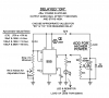
I want a 555 timer circuit diagram , which will result in turning an LED ON AFTER a time delay, but staying on permanently.

In other words, i want a circuit that will do the following

I push the trigger, then there is a time delay where the LED is off, then after the delay, the LED is turned on, and remains on. It is aimed as a one time use, its use in my project is only required to turn on automatically once, then i can reset manually for the next time.


SO i have gotten clear what it is that i want to happen.
Please, if its not to inconvenient for anyone, could you write up or find me a 555 circuit which will do just that. Its important that the led is OFF for the delay, then ON permanently, not ON during the delay, then switched OFF.

Anyway, please help if you can!
 
Look at this option.
 

Attachments

  • AAesp01.gif
    AAesp01.gif
    42.9 KB · Views: 3,785
Here is a simple circuit for you to play with,you may need to play with the 555 timing .
 

Attachments

  • DELAYED 555.pdf
    15 KB · Views: 4,044
thankyou both, im going to have to learn some more about reading circuit diagrams like that, im more used to seeing the components on a diagram as a representation of the component, like in any non electrical diagram.

Just one question, where do i find those parts? the NAND gate and transistors? theres not really allot for me to go with here, im very new to all this and i cant immediately tell what specifications the parts require, nor what the part number is ect.
 
Last edited:
Hi Joe,

here is a PCB design so you get an idea what the parts look like for your project.

PCB dimensions are 2.5625X1.4375".

Boncuk
 

Attachments

  • ANZ-VERZ-REL-BRD.gif
    ANZ-VERZ-REL-BRD.gif
    29.9 KB · Views: 2,102
Last edited:
the nand is a 4093 quad 2 ip schmidt trigger nand gate,theres a ne555 timer-all parts are readily available
 
This circuit is SIMPLE and gives a Delay Before turning on.
 

Attachments

  • DELAYED-ON.PNG
    DELAYED-ON.PNG
    7.7 KB · Views: 18,273
your right, it is, however i think ill build both, since i already bought the parts.
i dont understand though how such a simple design exists yet others suggest i use the NAND gates and make it overly complicated. though that must be the price to pay for a reset button.
your certain this is low during the delay, and high at the end? just checking, it looks to good to be true
 
I don't know if you have already bought components for this, but I would recommend using a 555 monostable and then using a D-type flip-flop to latch onto this, this flip-flop also has a "reset" pin, making it much simpler and cost effective than the other diagrams. Some simple googling would help in your search. :)

I will post a diagram for you as soon as I have woken up properly ;)

You probably have overlooked post #2 (ericgibbs). He suggested almost the same as you did with the exception that he uses an RS-flip flop instead of a D-flip flop.

So why do you think your circuit is more cost effective?

Boncuk
 
Last edited:
My idea would be like use a 4060 Circuit to turn ON the IC555(after a certain delay). And 4060 circuit should be designed based on that delay needed. It's a bit complicated and also bit costlier compared to previous ones. But Might Work, mostly when the delay is too large.

Hi Eric,
I didnt understand how your circuit works. Can you tell me how?
Also anyone tell me how #9 circuits work.
@em2006, but where does it produce a delayed o/p?

Hi Boncuk,
Your Idea seems to be similar to mine?
 
Last edited:
Ok, took me the morning but I did a diagram for you. I have also annotated it. (because I'm nice :D)
 

Attachments

  • Screen Shot 2011-12-23 at 12.35.15.png
    Screen Shot 2011-12-23 at 12.35.15.png
    159.9 KB · Views: 1,545
hi,
You are not showing the 74HC08 on your parts list, which means that 3 extra IC's are required.
The Reset pin on the 4013 is floating
There are also no power rail decoupling caps shown.

Using the circuit in post #2, only 1 additional IC is required.
 
making it much simpler and cost effective than the other diagrams.

I don't find where the circuit is more "cost effective" than the one already posted (#2). Please explain.
 
Boncuk: I thought it could be accomplished with just a monostable and latch... I guess I was wrong.

You are not showing the 74HC08 on your parts list
The NOT gate is in the 7404 chip, isn't it?

The Reset pin on the 4013 is floating
Also, the reset pin of the 4013 is connected to the reset switch, as mentioned in the diagram, if you are referring to the other Q, that is "Q-bar" - the inverse of Q.

There are also no power rail decoupling caps shown.
And I'm sorry, I don't know what you mean by this.

If I'm wrong, please don't flame me, just say why I'm wrong. Thanks :)
 
Status
Not open for further replies.

Latest threads

Back
Top