Continue to Site

Welcome to our site!

Electro Tech is an online community (with over 170,000 members) who enjoy talking about and building electronic circuits, projects and gadgets. To participate you need to register. Registration is free. Click here to register now.

  • Welcome to our site! Electro Tech is an online community (with over 170,000 members) who enjoy talking about and building electronic circuits, projects and gadgets. To participate you need to register. Registration is free. Click here to register now.

How do I create a zero-crossing delay in an alternating polarity square wave?

Status
Not open for further replies.

Urbanebassman

New Member
Hi Forum Members,
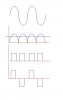
As newbie I would be really grateful for any advice on how to create a variable delay (ie zero volts for x milliseconds), at the zero crossing point of a positive-going square wave and the following negative-going square wave:
_______ _______
| | | |
|.........|..........|..... > |.........|__..............
| | | | |
| |______| |______|

Is it possible to do this with simple IC's like 555 timers, zero crossing detectors or logic gates?
 
Last edited:
The drawing is unclear. Can you post the waveforms as a gif file?
 
Thanks Guys,
Apologies for the diagram, it does not translate easily if I attempt to draw the waveform using the cursor keys! Here is a GIF attachment showing my present waveform and that which I hope to achieve. The pulse width is 10 to 15 mS and the PRF is 10Hz, with a delay (preferably adjustable) from 0 to 10mS.
Is this achievable without using DSP?
Regards,
Bassman
 

Attachments

  • Biphasic Waveform with delay.GIF
    Biphasic Waveform with delay.GIF
    2.4 KB · Views: 205
Better pic, but alas still not clear what you're trying to achieve. Your lower waveform is both shifted and of different shape. If you shift all the pulses the same amount without changing the pulse widths the shifted wave should be the same shape as the original.
Could you perhaps extend the number of cycles a bit in your pic, and add some vertical time-lines for us to see what aligns with what?
 
Last edited:
you may think of analog way, make a filter so that you will get a sine wave, then rectify it and make a wave form of PWM, then think of some way to invert every other pulse, may work? see the pic attached.

or you can rectify both sides separately and make an accurate pulse width.
 

Attachments

  • signal processing.JPG
    signal processing.JPG
    14.7 KB · Views: 166
Last edited:
Thanks Guys for the feedback. I was thinking along the lines of
**broken link removed** using a 555 timer
triggering on the negative-going edge of the waveform, with the output of the 555 inverted, then used to switch two npn transistors to switch off the +/- supplies to an op amp buffer, through which the signal also passes, giving the required delay by effectively switching the op-amp off for a time period dictated by the pulse width of the 555 output, which is adjustable. clearly, a similar circuit will be needed to perform the same operation on the rising edge of the next negative pulse. Any comments?
 
I may be able to get your waveform using the circuit that I suggested by feeding the top wave form into a tristate buffer non-inverting and use the second signal into the tristate control pin (TTL).
This will allow you to have thee levels of votages as dipcted in your Diagram,Hence tri-state.
Or you could mix the two signals together and use a level shifting technique on one of the signals such as that used to mix vertical sync pulses with horizontal sync pulses in video circuits.
look up the tvt-6 by don lancaster and you should find what I am talking about.

jer :)
 
Q: Does the waveform amplitude have to be preserved, or is it ok to do all this digitally? In other words, is it only the timing of the leading and trailing edges of the pulses which is important?
 
While you don't mention amplitude or frequency my guess is you are after what is commonly called a Modified Square Wave among other things like Quasi Square Wave. I have even herd it called a modified sine wave. The wave shape is popular in inverter designs among others. This is a link to a circuit that uses a uC chip to generate the wave form. However before the linked circuit used a PIC Chip uC it was done using a 555 timer with a 4017 counter. This is a link to the 555 and 4017 version. Note how the 4017 counter is used. Anyway, that may (or may not) be what you are after.

Ron
 
Hi,
Thanks foy your replies. Food for thought.
Yes, the waveform shown is the carrier wave for another square-wave frequency of 500 - 2.5KHz. So the total signal consists of an alternating polarity LF square wave, +/-12V, with PRF user variable from 0.5Hz to 10Hz, pulse width 10 to 15mS, mixed with an AF square wave signal, amplitude 12V. The desire is to introduce a variable (OV) delay of several milliseconds as the falling edge of the carrier wave hits 0V, befor it falls to -12V. Similarly, to create an equal delay as the rising edge at the end of the negatve pulse hits 0V, so delaying the next positive pulse.
 
Is this what you're after?
U1 forms an oscillator where R2 and C1 set the required pulse delay and R1 and C1 set the repetition rate to twice the desired rate. The Dflop then halves that rate. C2 attenuates spikes (arising from gate delays) at the 0V cross-over points.
The oscillator could be replaced by a PWM IC.
In the simulation the delay has been deliberately exaggerated to show up the waveform better.
 

Attachments

  • ShiftedSquareWave.gif
    ShiftedSquareWave.gif
    24.7 KB · Views: 183
  • ShiftedSquareWave.asc
    3.9 KB · Views: 152
Last edited:
Status
Not open for further replies.

Latest threads

New Articles From Microcontroller Tips

Back
Top