Electro Tech is an online community (with over 170,000 members) who enjoy talking about and building electronic circuits, projects and gadgets. To participate you need to register. Registration is free. Click here to register now.
Welcome to our site! Electro Tech is an online community (with over 170,000 members) who enjoy talking about and building electronic circuits, projects and gadgets. To participate you need to register. Registration is free. Click here to register now.
Close is good.
In my experience in the past with 8051 and PICs I always kept them within an inch of the pins but why would you want to place them further away anyway?
I used crystals of about 4MHz so placement may be more critical at higher frequencies.
yea I'm making veroboard "modules" with the pic on it and a power led and from your replys when needed the quaz circuit.
these I will plug into the "main" circuit board this was I can remove it program it and replace it and replace with a different pic if I want to I'm making one with a zif socket on it for prototyping etc.
alog the same quesrion line how long can the wires/tracks be btween the pic and the rest of the circuit ?
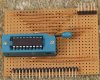
just so you can all scream at the many mistakes I made and probably never thought of heres a picture of the zif module.
this was basically so that I could program a pic or rather just connect it to the compter (via pickit 2) and see that I've accomplished some small deed in the pic world.
the lower header will plug into the "mother board" and the header at the top is to connect the pickit 2 to it.
so that I don't end up making every "pic module" that large I will (when they arrive) put a soket above the lower header so that a similar board (with a pic soldered straight to it - or on a normal cheap socket) can plug into it and be programmed from it without keep wiring the 6 pin header for the programmer on every module making the others smaller and saving a 6 pin header every time
I'll probably add a power led to this one just for kicks
You might run into some noise issues with the crystal being mounted farther away from the PIC like that. Now that you've built it try it out, but just be aware of the possibility so you can minimize trouble shooting time.
For in circuit programming you might want to look into a chip clip: **broken link removed**
And/Or some of these: **broken link removed**
You can save a pin and get away with the piezo device being much further away if you use and oscillator instead of a crystal. That way the oscillator, which contains the crystal, has the oscillation amplifier right next to the crystal and what goes along the wire is a buffered signal, so it should be no more sensitive to long tracks than any other digital signal.
whenever did I say I was using a 16F84 ? thats a 16F628A in my picture I didn't even bother to order any 84 infact you can't get samples anymore. I'm just thinking all options as I'm creating my own modular system.
I have found one solution: the osc1 & 2 pins are 15 and 16 the way I made my prototyping module pins 1-9 are on the closer side to the header and 15 & 16 are far away, if I turn the pic over and put it on the righthand side of the board it will put pins 10-18 nearest the header but keep the same header pinout I started with
well that board really is to program the pic via the pickit programmer that does not have a zif on it. I don't think a standard IC socket will take much putting in and out plus I'd end up damaging the pic so came up with the mudule idea, I'll just solder the pic to the board on other modules and plugit into the cicuit, thats for testing and experimenting, if I were to make a project into complete usable form I'd put the pic straight on the mainboard via a socket and implement ICSP
well that board really is to program the pic via the pickit programmer that does not have a zif on it. I don't think a standard IC socket will take much putting in and out plus I'd end up damaging the pic so came up with the mudule idea, I'll just solder the pic to the board on other modules and plugit into the cicuit, thats for testing and experimenting, if I were to make a project into complete usable form I'd put the pic straight on the mainboard via a socket and implement ICSP
Simply fit a normal socket on the board, and fit your working PIC with a turned pin socket, these have nice straight pins, and can be inserted and removed many times with no damage to the socket on the board, or the turned pin socket on the PIC (the PIC pins can't get damaged, because they are only ever inserted in the turned pin socket the once.
I've been doing this for teens of years, and have NEVER broken a PIC pin, a turned pin socket, or the socket on the target board.
If you're concerned you might consider ICSP and program the chip while it's in the board instead - but your current idea seems clumsy and probably as bad a choice as you could make?.
I think Nigel is right here; you want to save a fifty cent header on your boards, every time, but would instead spend a lot of extra time plugging and unplugging your chips to program them. Just put a header (or find a cheaper solution, or use the chip clip idea kchriste presented, to program) on your boards, and never have to plug in and pull out your chips, so never damage the pins that way.
Want one more? You'll need a pullup 22K is PICkit2 recommended for MCLR or your PIC won't run (unless you enable RA5 as an input, which doesn't work with the debug mode though)
This site uses cookies to help personalise content, tailor your experience and to keep you logged in if you register.
By continuing to use this site, you are consenting to our use of cookies.