Continue to Site

Welcome to our site!

Electro Tech is an online community (with over 170,000 members) who enjoy talking about and building electronic circuits, projects and gadgets. To participate you need to register. Registration is free. Click here to register now.

  • Welcome to our site! Electro Tech is an online community (with over 170,000 members) who enjoy talking about and building electronic circuits, projects and gadgets. To participate you need to register. Registration is free. Click here to register now.

How can I turn a continuous but press into a 5 sec pulse?

Status
Not open for further replies.

FreeZey

New Member
I'm currently trying to built a simple circuit that converts a continuous close into a 5 second pulse. I.e. if the circuit is closed for more than 5 seconds it automatically breaks/opens again.

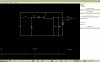
I’ve done an illustrating of what I’m after below:
PHP:
KEY:
  0v = _
       _
1.5v =

n    = 5 seconds

EXAMPLE:
            _________________       __
INPUT    __|                 |_____|  |___________

            _______                 __
OUTPUT 1 __|       |_______________|  |___________
(Okay)
            _______                 _______
OUTPUT 2 __|       |_______________|       |______
(Better)          
           |<- n ->|               |<- n ->|
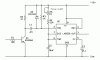
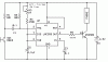
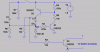
I’ve done a little research and it looks like a 555 timer, resistor and capacitor wired correctly might be able to provide this behaviour. But I’m not sure if this is correct or if it is what the circuit would be and the exact components I should be using.

Any help is appreciated.
 
It will need to be just a little more complex than a single 555. For the first pulse, when the timer times out after "n", it will trigger again, as tehpulse is still active. You may be able to use a capacitor on the trigger pin so that the timer only fires when the input makes a high to low transition. In that case, a 555 configured as a one-shot with a period of "n" would be appropriate.

You'll also need to invert your input signal, as the 555 fires in a low pulse.
 
Last edited:
I don't know what supply voltage you have or what output voltage you need, but this should give you a fixed output pulse length triggered from the leading edge of your 1.5v button press signal.

Ken
 

Attachments

  • 555 Monostable 5 Sec.gif
    555 Monostable 5 Sec.gif
    13.6 KB · Views: 253
Thanks for the quick responses.

I think a one shot looks like what I may need but it also looks like I'm going to need 2 separate power sources. I.e. the one used to monitor and act as the trigger and the second being the one which gets activated for 5 seconds. Which makes sense, but its a shame there's no simpler solution.

My actual circuit is something I rigged up with an old mobile as a primitive alarm. When someone opens my door it completes a circuit which I extended from the 5 button, causing it to speed dial my phone. I'm guessing the voltage going through the keypad is very low. Anyway the mobile is plugged into a charger so it don't have to worry about changing batteries or anything so if I could have one this without rigging up something with batteries it would have been nice.
 
The trigger voltage to the input transistor can be anything greater than +0.7V. A CMOS LMC555 will operate on a supply down to 1.5V. It might help if you can post a schematic of what you have now.

Ken
 
So, i had this great idea for how to do it, but it has one problem. if you rapidly press and release the switch the output will stay high. if that is not a problem this circuit might work. i haven't tested it outside the sim(which is not perfect).

Other then that, it works pretty well in the simulator, and has very few parts.(no triple 5 timer needed)
because its a potentiometer setting you can calibrate it to be exactly the pulselength you want.


the potentiometer sets the pulse time (and yes a short pulse will create a 5sec pulse)
 

Attachments

  • pulseout2.JPG
    pulseout2.JPG
    79.1 KB · Views: 208
Last edited:
The circuit isn’t very complicated as all the components are wired in series. This is the best diagram I can manage at the moment I’m afraid:
PHP:
 __ 
 | |
 | [Reed Switch]
 | |
 | [Rocker Switch]
 | |
 | [Phone Button]
 |__|
Reed switch
This is the trigger for the alarm. It’s always open while the magnet/door is next to it. However the one I brought can be set to the reverse as well, should the design require it.

Rocker Switch
This is located externally so that I can break the circuit to avoid setting off the alarm myself. I.e. most alarms have a proper system with a delay and a pin number to disable
them, this is my cheap alternative.

Phone Button
This is probably better thought of as a battery and an LED or a battery and a buzzer. Since what the phone does isn’t really important it’s just a power supply and alarm, waiting for the circuit to be closed.
 
So what's the power supply voltage? Do you want the reed switch at the input of the timer circuit and the rocker and "phone" at the output?

Ken
 
I think the voltage is between 3v and 3.7v but I can't check until Friday.

The reed would go before the input and the rocker after the output but I'm not sure why the rockers location matters, unless I'm going to need 2 circuits.
 
It's just a choice. The LMC555 should work at that voltage. Will the phone circuit be powered from that too?

Ken
 
I think my problem is this:
The phone locks together both the power supply and the result I'm trying to control, in one single unit.

So I can't have a separate trigger circuit that is always on and detects a change (the reed switch altering the voltage) because in order for that circuit to work the current has to return to the power supply and the only route is through the phone...which would complete the circuit I'm trying to control with the output.

I.e. I don't have a situation like the one below because my "battery" and "phone" must always be connected in immediate series :(
PHP:
 ----------[reed switch]------
|  |                          |
|  |     ________________    [battery]
|  |    [                ]    | 
|   ----[trigger         ]---- 
|       [                ]
 -------[                ]
        [    LMC 555     ]
        [                ]
        [                ]
    ----[output          ]-----
   |    [________________]     |
   |                           |
   |                           |
    ----------[phone]----------

So I can't get away without a second battery? Due to the wiring limitations of the phone.

...unless I can find somewhere on the phones circuit board to steal a nice little 3v supply.
 
Do you mean that the phone must have the pos and neg of the battery connected at all times? If not, maybe this? The reed switch is a normally-open in this case. I don't know how much current the phone uses. I didn't include the rocker switch.


This assumes you can leave the battery positive to phone positive and switch the negative. If that won't work you would need another transistor and two more resistors.

Ken
 

Attachments

  • 555 Monostable Phone.gif
    555 Monostable Phone.gif
    15.3 KB · Views: 213
Last edited:
This might illustrate what I'm doing better...
**broken link removed**

I forgot I had this picture. As you can see I've just run a couple of wires off the switch below the 5 button on the phones key pad, so when they're touched together it replicates someone pressing down the number 5.

If the circuit is closed for more than 3 seconds it speed dials 5, which is my phone.
That's all okay and if I extend these wires and put a reed switch in I can get it to call me when the door is openned.

With that in mind do people think I can do this without a second power source? I'm sorry I've been trying to read the circuit diagrams but it's hard to get my head around this stuff.
 
Last edited:
You can just add a small relay and just connect the two wires to the contacts. That would be the same as having them connected to the reed switch.

'Course, you'd still need the 2nd power source.

Also, you could just power the electronics off the wall wart your phone pluggs into. Just cut the wires running to your phone and solder a second set in a "Y" fashon, one set to the phone and the other set to the timer. You might need to add a capacitor to your circuit if your adaptor isn't already filtered.
 
Last edited:
I agree with BrownOut...unless there's something else we don't know.

Ken
 
Thanks for all the advice, I shall do some further research to check voltages and see if I can steal power from my phone charger.
 
It should be possible to use a transistor to activate the phone instead of a relay. It's also quite easy to design the pulse extender circuit to draw a small enough current to allow it to last for a few years from a single AA battery.

It might also be possible to power the pulse extender circuit from the switch contacts themselves, depending on how the phone scans the keys. Using a diode & capacitor to take the power from the key mux and a mosfet and some RC for the rest. I have to go to work now, but I'll draw it up (if it's simple enough) if you don't get another solution in the mean time.
 
Here's a low-power simple pulse extender - has virtually no current idle consumption so you could run it from a calculator cell for the shelf life of the cell.

With the values shown, the on time is around 5 seconds & the retrigger delay is something like 1-2 seconds.
 

Attachments

  • pulse extender.gif
    pulse extender.gif
    9.4 KB · Views: 156
Status
Not open for further replies.

Latest threads

New Articles From Microcontroller Tips

Back
Top