Electro Tech is an online community (with over 170,000 members) who enjoy talking about and building electronic circuits, projects and gadgets. To participate you need to register. Registration is free. Click here to register now.
Welcome to our site! Electro Tech is an online community (with over 170,000 members) who enjoy talking about and building electronic circuits, projects and gadgets. To participate you need to register. Registration is free. Click here to register now.
You need to know your input, transistor parameters, and output in order to calculate anything. I would look into "Transistor Biasing" to start out with. I know that MIT has some good video lectures on the subject, except with MOSFETs. Ideally, you should be able to learn about MOSFETs and apply the fundamental concepts to BJTs.
First experiment or look up on a data sheet, the amount of current and the voltage drop across the output device.
That current will be (Io) and the voltage will be (Vo).
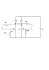
It looks like each transistor turns on a light bulb. The datasheet for the 2N2222 and most other transistors shows a low max saturation voltage loss when the base current is 1/10th the collector current which is the light bulb. You cannot calculate the value for R1 and R2 unless you know the resistance or current of each light bulb. Then R3 and R4 are a much higher value like 10k ohms.
Ok. From the initial values you gave I am not clear if they are given in the problem or if you just used the datasheet. The reason for this is that you mention E=5 [V], but also mention VCE=30 [V] from where does this additional voltage appear?
By taking a look at the circuit, if you find the values for one of them, the other should be exactly the same. Remember you already have Ic and Hfe, that should give you a start for finding Ib.
hFE is used for a linear amplifier transistor that has plenty of collector to emitter voltage (10V) when it is turned on. But these transistors are not linear, they are used as a switch with a very low collector to emitter voltage when turned on. So hFE is not used but the spec in the datasheet about the saturation voltage is used instead where the base current is 1/10th the collector current.
The circuit operates from a 5V battery (E). The max allowed VCE voltage of a 2N2222 transistor is 30V which is not used here.
This site uses cookies to help personalise content, tailor your experience and to keep you logged in if you register.
By continuing to use this site, you are consenting to our use of cookies.