Continue to Site

Welcome to our site!

Electro Tech is an online community (with over 170,000 members) who enjoy talking about and building electronic circuits, projects and gadgets. To participate you need to register. Registration is free. Click here to register now.

  • Welcome to our site! Electro Tech is an online community (with over 170,000 members) who enjoy talking about and building electronic circuits, projects and gadgets. To participate you need to register. Registration is free. Click here to register now.

How can I do this

Status
Not open for further replies.

BBQTime

New Member
Hi everyone

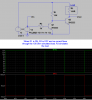
This is what I'm looking to do....I have seen somewhere but can't now locate on google a 2 or 3 transistor circuit that when it receives a 12v current via a 1k base resistor it will start conducting and switch the other transistor / transistors off thus disconnecting the supply to the given circuit....


Hope I explained it properly sort of a "normally on" transistor and a "dump" transistor obviously I just want to disconnect the supply to a 2nd circuit controlled via this one,the circuit I want to switch off uses around 125 mA

Ps I don't want to use a relay to do this and if I remember correctly the transistors used were PNP 2n2222 I think?...I posted on another forum so I'm looking for other ideas.

Thanks
 
Last edited:
The 2N2222 is actually a NPN transistor capable of a collector current of about 800 mA. While I am not sure exactly what you have in mind the below circuit may help. The circuit uses two NPN 2N2222 transistors. Voltage V1 simulates your 12 Volts and Voltage V2 is just some pulsed 12 volts to simulate turning Q1 on and off, when the base of Q1 is high it holds Q2 off, when the base of Q1 is low it allows Q2 to be turned on. Resistor R3 simulates a 100 Ohm load being turned on and off. So when Q1 is ON then Q2 is off and the load is off, when Q1 OFF then Q2 is On and the Load is powered.

Ron
 

Attachments

  • 2N2222 Cascaded.png
    2N2222 Cascaded.png
    22.6 KB · Views: 216
Thank You Mosaic. Reloadron I think that's exactly what I want when Q1 is on Q2 is off resulting in the load / Circuit turning off...I will give it a try and get back to you when I finished work ....Cheers
 
Q2 is allowing 3.7 v the circuit that I want to switch off is still on any suggestions .....thanks again
 
Whats the base voltage of Q2 when you're getting the 3.7V across the load?
Perhaps Q1's base is picking up some 'noise' somehow. Place a 1K pull down to ground resistor on its base.
 
Q2 Base is at 0.77 v this is the sensor i need to cut the supply to there is 5 in total .......**broken link removed**.

Cheers
 
The way the cct is setup if Q2 is biased on then Q1 is biased off (no 12V input). To switch Q2 off you must apply the 12V to Q1 base.
Is this how you want it to work?
 
Q2 Base is at 0.77 v this is the sensor i need to cut the supply to there is 5 in total .......**broken link removed**.

Cheers
It does not say how much power your sensor needs, you say "around 125 mA", maybe its less?
Did you try the pull down resister on the base of Q2.
 
Used the pull down resistor.... voltage out at Q2 5.05v..... I believe these sensors can work at 3.3 v by the ebay listing
 
Used the pull down resistor.... voltage out at Q2 5.05v
What was the base voltage? should be 0 with the pull down.
Did you have a load on Q2 when you measured 5.05? the voltage will float without a load.
 
Yes it could be less 4pyros there is also an led plus buzzer for each one
With all that times 5 you may overload Q2, you may need a bigger transistor.
Can you measure the load of one sensor setup with the LED and Buzzer on?
 
A buzzer can produce a bunch of back emf. You may need a rev biased diode across that buzzer.
 
The sensor is a digital unit.
It's possible it has weak pull ups etc on the PCB. Thus you can have a power leak from the digital (i2c/spi) lines showing up on the power pins even with no help from the 2n2222.

Try out the circuit with a standard 'load' like a lamp or a resistor (100 ohms). If it still has a prob with switching off. Measure the Vbe and Vce of each transistor and post it here.
 
Status
Not open for further replies.

Latest threads

New Articles From Microcontroller Tips

Back
Top