HI im new her and i wont ask for help...
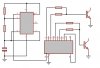
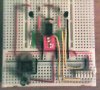
i want to build a flasher (like in the video) but i n00b in electronics and mine english very poor.
so if some one can please help i will be happy and thankful.
here is the video (youtube): https://www.youtube.com/watch?v=adqpnVcVtfs
it is a PIC???
Thank you all
i want to build a flasher (like in the video) but i n00b in electronics and mine english very poor.
so if some one can please help i will be happy and thankful.
here is the video (youtube): https://www.youtube.com/watch?v=adqpnVcVtfs
it is a PIC???
Thank you all