Continue to Site

Welcome to our site!

Electro Tech is an online community (with over 170,000 members) who enjoy talking about and building electronic circuits, projects and gadgets. To participate you need to register. Registration is free. Click here to register now.

  • Welcome to our site! Electro Tech is an online community (with over 170,000 members) who enjoy talking about and building electronic circuits, projects and gadgets. To participate you need to register. Registration is free. Click here to register now.

How can I build a CMOS current generator ?

Status
Not open for further replies.

malc9141

Member
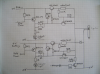
I have an experimental 2-stroke diesel engine. The Delphi injection system operates over less than a millisecond. A pulse of high current (about 16 A) at 24 v is generated and 'fired' with a switching inverter circuit, whose duration can be varied. This is the"accelerator."

I am not in any way an electronics expert (advanced schoolboy physics helps but little).

I published details of our circuit on wordpress.com/malc9141.

It's pretty clumsy and I was told a CMOS circuit would be better for the current generator (igen) segment.

(There are two igens in my circuit, one for Fire, the other for Hold; but if I began to understand a single igen, it would be a great help).

I have two lead-SO4 batteries in series, with a 22000 pf cap, as the source of power. The timer circuit allows a transistor BFR39 to earth (for the timed moment). This activates the igen.

Would it be possible to start discussing how I could build a CMOS igen?
It's no use having flippant one line answers, so if that's what's on offer, just relax! I need a lot of precise help; it would be a conversation.

Thanks

Malc
 
It would help us if you could post the circuit here, or a link direct to the circuit. Forum members will not want to wade through ads and a blog just to find the circuit.
 
Thanks. Alex

The circuit has three parts, each doubled.
But only the last part, with the injector, matters for the question,.

This last part is (as I've said) "doubled."

1)When the injector is fired, a huge electrical pulse (about half a kW for <millisecond,) opens a ferrite solenoid valve, and the incredible hydraulic pressure (how about 1500 bar, and more!) bangs open the needle valve, squirting in fuel, in a millisecond or so.
2) Having opened the needle valve, the current drops back to a hold value (about 5 A).

This can be found with some fiddling at www.malcolmcochran.wordpress.com.

You might have to look on the "earlier blogs" or similar. Wordpress is a bit weird.
It's under Delphi fuel injection system. It's not "Block Diagram"
which I couldn't load.
 
Actually that is not a bad circuit if you need the adjustability and the current limit.

It's now attached for others.
 

Attachments

  • current-gen.png
    current-gen.png
    2.2 MB · Views: 295
Actually that is not a bad circuit if you need the adjustability and the current limit.

I agree, that seems a perfectly fine circuit, although I don't quite see what the preset resistors actually change?.

I don't see how a CMOS circuit would make any difference?, or why anyone would suggest such a thing?.
 
I was told the CMOS circuit would get rid of the big MJ 15003, using lots of current. We could make it all neater.

I know this circuit works - we started not knowing what was needed - the required charge pulse turned out to be immense. Who would have known (the pots were part of this experimentation) ? Telling me it works is no answer.

But this is what I feared: nothing much that helps.

How could we design a neater circuit, knowing that this does work even if it looks like an octopus?
 
Last edited:
Unless you are considering a PWM approach to controlling current, a CMOS circuit (i.e. a logic circuit) has no obvious purpose here. Perhaps whoever suggested it intended 'FET'. You could replace the MJ15003 + BD7N + 390R with a FET....not much neater, and any current saving would be minimal.
A CMOS circuit would not be able to run directly from 24V, so that would require additional components to drop the voltage.....hardly a neater solution.
In summary, what you've got looks fine (as stated by others). If it ain't broke why fix it?
 
Thanx - that's useful. I'll bear that in mind. You could be right.
The 24V was part of the argument, but I was led to believe it would be more compact.

The existing circuit is mostly reliable but now & again, something goes wrong, and a couple of ICs burn.
I want something more robust if I make another. Not wires going everywhere.

But maybe it wouldn't help. But anything you or others can add, will help. I will have to find out what FET means!!!! Shows how much I know.
 
I was told the CMOS circuit would get rid of the big MJ 15003, using lots of current. We could make it all neater.

If someone told you that?, why didn't they do it for you?.

As already mentioned by alec_t, there's no 'magic' reason for a CMOS solution to be any better, and it's likely to be more complicated for no advantage.

I know this circuit works - we started not knowing what was needed - the required charge pulse turned out to be immense. Who would have known (the pots were part of this experimentation) ? Telling me it works is no answer.

But this is what I feared: nothing much that helps.

How could we design a neater circuit, knowing that this does work even if it looks like an octopus?

It's pretty neat already, simple current limited power supplies - the current is limited by the value of the 0.2ohm resistors, and will be roughly 3-4amps.

FET is 'Field Effect Transistor', and isn't likely to be of much help to you.

What IC's fail?, in what way?, and does anything else fail? - bearing in mind there's no IC's shown in the circuit you posted.
 
I don't see how a CMOS circuit would make any difference?, or why anyone would suggest such a thing?.

I wondered that myself. There does seem to be a way to simplify it though. You have two seperate but identical circuits with their outputs "wire or'd" together. Why not have just one circuit and "wire or" the inputs from the timers?

EDIT: After readingthe link, I realize the two circuits aren't identical after all, though the schematic doens't show the difference.

EDIT2: I see no reason to resistively divide the voltage across the output reisitor. You can eliminate the the 33ohm and 100 ohm reisistors. That might make it a little neeter.
 
Last edited:
You might make it slightly simpler by swapping out the MJ15003 and BD711 with a darlington like a MJ11016.
 
Thanks, BrownOut

It's good that you all seem to think we have it right. I couldn't see what a CMOS would do, but I didn't understand it, either. So I'm getting a "second opinion" !

It's a bit confusing: I wanted to be able to inject at two points in the cycle, not just one. In modern VWs, Alfas, etc. they inject a tiny bit of fuel (too little to catch fire) long before TDC. This creates perfect atomisation of fuel (essential in diesel) and helps burn the main charge.
So I have two inputs from the crank. Diagram on web but not shown here.
Each of these can "fire" the main igens. These send the charge to the solenoid in the injector. Now forget about that!! :)

@your edit 1. There are 2 igens and number 1 opens the valve, number 2 holds it open. That's what we have here. As the big charge fades the holding current takes over. Total time about 1.5 msec.

@ edit @.Thanks. I'll think about this (as best I can).
 
What IC's fail?

Well, it's all about "reality". I don't think my argument is very good, actually.

We have an engine and a desk with the circuits on it. On a board. Mostly it's reliable. But I have a point where 4 wires have to be kept separate. Fine, till some jerk, bump, causes a short. End of IC. I would like a three or four pin plug; to allow me to join wires without soldering and insulating (which is what mysteriously fails - about twice in a few years!).

I just want to make it all more rugged.
 
malc9141 said:
@your edit 1. There are 2 igens and number 1 opens the valve, number 2 holds it open. That's what we have here. As the big charge fades the holding current takes over. Total time about 1.5 msec.

Your approach to the design is, I would say, the best in terms of getting something that works reliably. There are some optimizations that can save a few parts, but I'm afraid the effort and risk are more than the rewards. If you decide to go into production and have a developemnt budget, then maybe it would be worth it, but I don't see at this stage any reason to take the risk. Happy motoring :)

I just want to make it all more rugged.

Without analyzing your full design, I would suggest you research methods to remove or suppress spikes, noise and such from your system voltage rails. Also, make sure you know about "load dumps" Google has lots of info on that.
 
Last edited:
You might make it slightly simpler by swapping out the MJ15003 and BD711 with a darlington like a MJ11016.

I'll try to understand this.
I'm happy if it's as good as it gets. Thanx all.
 
I haven't yet looked up Load Dumps. But I suspect it'll be the reverse EMF when the voltage switches off. Bosch (but maybe not Delphi) cleverly harvest this in a cap, which gives a ?big (unknown) voltage for the next Fire.
I think we just drop this into 0v via a big diode.
I do wonder if it charges a cap (not shown) which we have across the battery output. I think it doesn't.

We do have a damper circuit which might take care of a Load Dump. However, homework is required.
 
To everyone: many thanks. It sounds as tho' I should just build a less amateur version of what I have, with maybe the minor mods suggested. Leads could plug in, and that would be it.
 
malc9141 said:
I haven't yet looked up Load Dumps. But I suspect it'll be the reverse EMF when the voltage switches off. Bosch (but maybe not Delphi) cleverly harvest this in a cap, which gives a ?big (unknown) voltage for the next Fire.

Not at all. In short, there are special considerations that are necessary when desinging for automotive applications. The 12V power is not 'clean' One big problem is load dumps, when the electrical load suddenly changes and the power rail surges over. Anyone who disigns for automotive has to consider these issues.
 
Ah, yes. We deliberately used 2 little 12V batteries in series to get 24v (we found a single one would not provide the opening speed - because I did know that although the magnetic strength was f(i), the development of it was V dependent.)
But the point was to keep an independent circuit, with a cap in place.
Just to avoid effects from elsewhere.

Anyone who disigns for automotive has to consider these issues Fair enough. I didn't know that - but fortunately we anticipated interference from spikes (?) - your term - from the main battery during starter motor use. So we used the little Lead-SO4 house burglar alarm units.
 
Status
Not open for further replies.

New Articles From Microcontroller Tips

Back
Top