Electro Tech is an online community (with over 170,000 members) who enjoy talking about and building electronic circuits, projects and gadgets. To participate you need to register. Registration is free. Click here to register now.
Welcome to our site! Electro Tech is an online community (with over 170,000 members) who enjoy talking about and building electronic circuits, projects and gadgets. To participate you need to register. Registration is free. Click here to register now.
Is it normal for a T0-220 type transitor to get very hot when running it at 12 volts @ 0.5 amps with heatsink?
The transistor is rated at around 3 Amps.
Even a T03 gets hot 12V @ 0.5 Amps ( no heatsink).
It's rated at over 10 Amps. :?
Is it normal for a T0-220 type transitor to get very hot when running it at 12 volts @ 0.5 amps with heatsink?
The transistor is rated at around 3 Amps.
Even a T03 gets hot 12V @ 0.5 Amps ( no heatsink).
It's rated at over 10 Amps. :?
Do the sums! - and check the specs on the transistors, bear in mind dissipation on power transistors is often given with the case held at 25 degrees centigrade, this is impossible to achieve in reality.
Assuming you have 12V across the transistor, and 0.5A through it, the transistor will be dissipating 6W as heat - bear in mind that's about 1/3 of many soldering irons!.
The dissipation depend from voltage loss on transistor.When this is a power supply with 20V input voltage and 12V output voltage and 500mA load, the dissipation is 4W.
When the transistor work as output switch with 500mA load, it must be saturated ( voltage between E-C about 0,5V) by high enough base current.
Assuming you have 12V across the transistor, and 0.5A through it, the transistor will be dissipating 6W as heat - bear in mind that's about 1/3 of many soldering irons!.
Later, I added a 9 volt regulator a between the transistor and 0.5 @ load.
(12volts straight thru PNP transistor , to 7809 voltage reg, to 0.5 amp load)
The transistor still got hot, but the voltage regulator did not.
how do you know what size heatsink is required for the amout of wattage.
my catalog shows them in Thermal resistance.
eg t03 type as 7.3 degreesC/W
What does that mean?
I notice that bigger heatsinks are rated with smaller values.
Assuming you have 12V across the transistor, and 0.5A through it, the transistor will be dissipating 6W as heat - bear in mind that's about 1/3 of many soldering irons!.
Because that's how the world works!, energy can be neither created or destroyed, only converted from one form to another - in this case electricity is converted to heat, using the formula W = V x I.
Later, I added a 9 volt regulator a between the transistor and 0.5 @ load.
(12volts straight thru PNP transistor , to 7809 voltage reg, to 0.5 amp load)
The transistor still got hot, but the voltage regulator did not.
That's because the regulator probably won't be doing much, you're not really providing it with enough voltage to work.
Please post your complete circuit so we can see what you're doing.
how do you know what size heatsink is required for the amout of wattage.
my catalog shows them in Thermal resistance.
eg t03 type as 7.3 degreesC/W
What does that mean?
I notice that bigger heatsinks are rated with smaller values.
It's fairly complicated to work out, personally I just try and keep things as cool as possible - I never bother getting involved with the calculations.
Is it normal for a T0-220 type transitor to get very hot when running it at 12 volts @ 0.5 amps with heatsink?
The transistor is rated at around 3 Amps.
Even a T03 gets hot 12V @ 0.5 Amps ( no heatsink).
It's rated at over 10 Amps.
You need to find out the maximum voltage, maximum current and the maximum wattage the transistor can handle. If your circuit delivers a current, voltage, or wattage exceeding that of the transistor, then it is normal for it to heat up.
Don't forget ohms law here: Voltage * amps = wattage
At least one of the ARRL Radio Amateur's Handbooks does a nice job explaining some of the complexities of heat sinking. They provide some procedures that are better than guessing. I posted a response this morning under "calculating heat" that touches on some heat transfer issues. Usually one goal of the design process is to determine within reason, the smallest or lowest cost part - in this case, the heat sink. If you look thru the material in the handbook you'll see why it might be simpler to make the sink really large - or experiment to get the answer. The level of effort required to make it just large enough might be more effort than it's worth.
You might also do some experiments and measure the case temp - comparing it to allowable temps. What you might think is too hot could be well within the allowable operating range. With that said, most professionals would probably tell you that cooler is better.
The transistor will be an electronic supply switch for a different circuit.
I'm trying to simulate a 0.5 amp load to see how hot my transitors will get at that load.
It's just simpler to use resistance wire instead of 25 leds, 10 ic's, 2 voltage regulators & , etc..
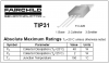
My original idea was to use a t0-220 type but it gets too hot even tho its rated at 40 watts with that little heatsink.
The transistor will be an electronic supply switch for a different circuit.
I'm trying to simulate a 0.5 amp load to see how hot my transitors will get at that load.
Calculations for a heatsink are simple:
A TIP31 medium-power transistor in a TO-220 case is rated at 40W if its case is held at 25 degrees C somehow!
It is rated at only 2W without a heatsink with an ambient temp of 25 degrees C.
In both cases its chip will be at its max of 150 degrees C.
If you mount it on a heatsink and the transistor feels warm then its case is higher than your body temp of about 36 degrees C and it cannot dissipate 40W without its chip temp exceeding its max.
From the transistor's chip to its case is a thermal resistance of 150 degrees minus 25 degrees divided by 40W = 3.125 degrees per Watt.
If you use a good thermal grease and bolt it to a heatsink, the mounting will have another thermal resistance of about 0.5 degrees C per Watt. If you use an insulator then it will also have an additional thermal resistance of about 0.7 degrees C per Watt.
If you use a heatsink rated at 2.0 degrees per Watt then the total thermal resistance is 3.125 + 0.5 + 0.7 +2.0 = 6.325 degrees per Watt.
Therefore the transistor's chip will be at its max of 150 degrees C in an ambient temp of 25 degrees C and there is free airflow around the heatsink (it is with its fins vertical) when the transistor is dissipating only 150 degrees minus 25 degrees divided by 6.325 = 19.8W.
Use a huge heatsink rated at only 1.0 degrees per Watt and the transistor with an insulator can dissipate only 23.5W.
Remove the insulator and use a huge heatsink rated at only 1.0 degrees per Watt and the transistor can dissipate only 27W.
Use a big heatsink and a high velocity fan but no insulator and the transistor can dissipate 34.5W. :lol:
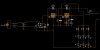
I'm going to call that big transistor Q1 and the base resistor Rb.
OK so you want to use Q1 as a switch for the regulator. I'm assuming Rb will be disconnected from ground by another circuit.
In this case read the voltage difference between the emitter and collector of the transistor. If it is much greater than 0.3v you have not given it enough base current and it is not being a very good switch. Rb is too large. Use a smaller resistor but not too small or you can exceed the "maximum base current" as listed in the transistor spec sheet. The current through Rb is (Vin-0.7v)/Rb. That means that the current through Rb is proportional to the source voltage. If it goes higher then it may make too much base current and if the voltage gets too low it may not be enough and stop being a good switch again.
Daniels,
In addition to D7:
1) Why use a transformer with a high voltage of 24V when the 7812 needs only 15VDC? 24VAC makes 32VDC when rectified and filtered.
2) Why is the value of C1 and C2 so high? Only 0.1uF is usually used but some people use as high as 10uF.
3) Aren't the LEDs very dim with such high values for their current limiting resistors? I figure red LEDs will get only about 1mA.
This site uses cookies to help personalise content, tailor your experience and to keep you logged in if you register.
By continuing to use this site, you are consenting to our use of cookies.