Continue to Site

Welcome to our site!

Electro Tech is an online community (with over 170,000 members) who enjoy talking about and building electronic circuits, projects and gadgets. To participate you need to register. Registration is free. Click here to register now.

  • Welcome to our site! Electro Tech is an online community (with over 170,000 members) who enjoy talking about and building electronic circuits, projects and gadgets. To participate you need to register. Registration is free. Click here to register now.

Homemade Function Generator

Status
Not open for further replies.

Kingpin094

New Member
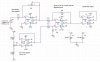
I am in the process of building a function generator that is loosly based on the the circuit below.
I was curious to know if there is any reason to use the TL072's in the circuit?
Could I replace them with LM324's? Does anyone know a replacement for the EL2001 can't seem
to find that output buffer any where. Or can I put a LM324 buffer there too? Circuit will be designed
for 1Hz to 1MHz so output frequency will not be that high.

Also does anyone know of a good way to give the output a variable dc offset?
I figured that I could stick and opamp on the end to give ~10Vp-p on the output and was hoping
that I could use the same opamp to DC offset thesigal by from 0 to 5Vdc.

Any suggestions comments would be greatly apppreciated.
kingpin094
 

Attachments

  • hsfglc11.gif
    hsfglc11.gif
    18.3 KB · Views: 2,463
Hi Kingpin,
If you use a quad LM324 or dual LM358 for the DC fine and course frequency control buffers, then their high noise level might cause the project's frequency to twitch. Certainly not for the output buffer, since they were designed for very low power (in their day) and therefore have lousy high frequency response. It will give hardly any output at 100kHz and just about nuthin' at 1MHz. I don't know about any other good buffer than the one shown. :lol:
 

Attachments

  • lm324.png
    lm324.png
    15.3 KB · Views: 1,383
The output from the MAX038 is 4Vpp.
To get 10Vpp you obviously need amplification and you also need higher voltage supplies. I would suggest plus and minus 9.
 
Thanks for the quick replies.

I was planning on running an output amp at +-12v to get the swing I want. So that part shouldn't be a problem.

Will the TLC072A replace the TL072? Looks about right.

Anyone know a replacement for the EL2001 can't find any data on in.

Thanks again
 
Looking through RS Components on-line catalogue http://rswww.com these look promising for the output amplifier:

Burr-Brown's OPA633 and BUF634 (according to the catalogue they're made by Texas too,) and Harris' HA-2841
 
I think I am going to go with the TLE2081 from TI. It doen't quite make it to 1MHz but i don't
think that i will use it at such a high frequency.

A few other questions. I am going to hook the function generator up to a PIC and a LCD so I can
see the frequency and the amplitude.

Is there an easy way to digitally control the range portion of the circuit?
Thought about using a cmos CD4060 swith but don't know if that will work.
I have some digitally control pots from Microchip that I was thinking about using in place ot the
mechanical pots bu they are only 256 step and I might want more frequency resolution.

What is a good way to add a DC offset to the output of the circuit?

Thanks again for the info.
kingpin094
 
Kingpin094 said:
What is a good way to add a DC offset to the output of the circuit?
Either a summing or a difference amplifier.
Buffer the offset pot with a voltage follower before connecting it to the summer otherwise the pot will affect the gain.
 

Attachments

  • sumsub.gif
    sumsub.gif
    5.2 KB · Views: 1,236
David Bridgen said:
Buffer the offset pot with a voltage follower before connecting it to the summer otherwise the pot will affect the gain.
Sorry, David.
1) On the summer, either input doesn't affect the gain of the other, so either input could be the signal and the other input directly from an offset voltage pot. The linearity of the offset voltage is affected by its load resistance so the pot might need a buffer for isolation.
2) On the differential amp, if the signal is connected to V1, then a pot on V2 won't affect the gain, but might need a buffer to be linear. :lol:
 
1) either input doesn't affect the gain of the other
Wasn't my intention to imply that.

2) a pot on V2 won't affect the gain
I'm guilty of excessive brevity, perhaps. Or, worse still, being imprecise.
Yes, it's the linearity which is affected - the gain of the particular loop effectively changing with the pot's rotation when it is not at either end of its travel.
 
Been a little while since I could work on this project but here is what i have come up with for the output stage.

Replace the uA741's with the TLE2081CPE4 from TI.
All pots are 10k linear.
And the DC offset only goes from -2.5v to +2.5v.

Does anyone see any possible issues with the circuit.


Thanks in advance
kingpin094
 

Attachments

  • output_stage.jpg
    output_stage.jpg
    56.9 KB · Views: 1,347
Status
Not open for further replies.

New Articles From Microcontroller Tips

Back
Top