Electronics4you
Member
Hi there,
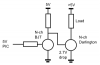
I need some inputs on how to supply a high current from a microcontroller. The setup is a high current darlington transistor (Ic, max=150A, beta=100) and a microcontroller to control it. With the transistor gain I need to supply 1.5 A. Can this be done using either darlington driver arrays or power transiors/MOSFETs without using small-Ohm high power resistors that eats up all the power?
Thanks