Continue to Site

Welcome to our site!

Electro Tech is an online community (with over 170,000 members) who enjoy talking about and building electronic circuits, projects and gadgets. To participate you need to register. Registration is free. Click here to register now.

  • Welcome to our site! Electro Tech is an online community (with over 170,000 members) who enjoy talking about and building electronic circuits, projects and gadgets. To participate you need to register. Registration is free. Click here to register now.

High Current Constant-Current Source

Status
Not open for further replies.

BrianG

New Member
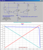
I need a constant current source able to deliver 15A. I know how to configure an LM317T as a CC source with the programming resistor between the output and adjust pins (and the power required, which in this case is 1.25v * 15A), and use a pass transistor to handle the extra current.

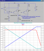
However, I'd like to use multiple PNP pass transistors to help spread the current (and thermal) load. I know that paralleling transistors directly is not advised without compensating for transistor variances by using a small value resistor. Most paralleled transistor circuits I've seen use this resistor in the emitter, but not sure exactly how it would work in this application.

BTW: I seem to have a ton of TIP127 PNP Darlington transistors for some reason, so I'd like to use those if I can.

Edit: Oh yeah, I did try the search, but the only results I seem to get are circuits for LED drivers - I know how to regulate lower currents... :)
 
Last edited:
Compliance? (max voltage you need at 15A?)
 
At 15A could you try taking a buck regulator IC and modifying the feedback resistors in some way? Obviously, a linear 15A current source is gonna make lots of heat.
 
What I'm making is a 12 cell Li-Fe battery charger for e-bike applications. A commercial charger capable of charging these at 15A would be quite expensive. So, I'm just going to do a CC charge until they hit 3.6v/cell and then the charge will terminate. These batteries don't take much charge during the normal CV stage anyway, so I'm not too concerned about getting every last mAh out of them.

I plan to use a 50v DC supply. Worst case, the batteries are at around 2.9v/cell, which is 34.8v. The transistors will have to bleed off around 14v. At 15A, that's quite a bit of heat at around 200w. But, I won't be filtering the supply so it'll be getting 15A pulses so that should help the heat somewhat. Plus, the cell voltage will rise fairly quickly reducing the differential voltage, so that 200w will go down to less than 100w pretty fast. Towards the end of the charge, the tranistors will be dissipating less than 80w. Yeah, that's still high, but my goal is circuit simplity over efficiency. This charger will be stationary in the garage, so size (for proper heatsinking and fan cooling) is not a concern. Besides, I have just about all the components I need right now in my parts bins.
 
Here is one way. Note the dissipation vs load resistance. You can parallel up to about 10 TIP127s; depends on how much current the opamp can sink.

Added: Rehash for 50V source, constrained the output voltage from 25 to 48V. Note how the voltage across the opamp is reduced.
 

Attachments

  • DF17.png
    DF17.png
    41.5 KB · Views: 1,986
  • DF17a.png
    DF17a.png
    44.3 KB · Views: 1,654
Last edited:
Good basic design to force constant current. You can push the TIP127's harder if you want to. Heat sink required, and Safe Area of Operation shows 5 amps each with 15 volts across the transistor. Their guaranteed minimum gain of 1000 means 15 amps out requires .015 amps in, distributed among however many transistors you use. Can an op-amp deliver 15 ma? Yes, you can get those. It's a lot to do about heat.

I'm going to stop and argue with my uploader for a while.
 

Attachments

  • TIP127.pdf
    611 KB · Views: 1,187
Mouser 532-633403U09 = 2.6 to 3.2 amps per transistor per 3 inch section of metal...depending on air flow from not forced to 400 ft per minute.
 
Pulsed dissipation is lower. You should be able to do this with an LM317 and some PNPs, as you mentioned.
 

Attachments

  • 15A pulsed current source I.PNG
    15A pulsed current source I.PNG
    23.9 KB · Views: 1,236
  • 15A pulsed current source TIP127 Pdiss.PNG
    15A pulsed current source TIP127 Pdiss.PNG
    17.7 KB · Views: 1,191
  • 15A pulsed current source.asc
    4.2 KB · Views: 619
  • 15A pulsed current source sch.PNG
    15A pulsed current source sch.PNG
    20.1 KB · Views: 2,252
Last edited:
Oh, I get it. Let the power line voltage frequency do the pulsing. Very slick!
It's not my idea.
BrianG said:
But, I won't be filtering the supply so it'll be getting 15A pulses so that should help the heat somewhat.
Of course, you don't get 15A average. You only get about 6.
 
Thanks for the responses guys! The schematic in Roff's post is exactly what I was envisioning, but was second-guessing myself. Let me see if I have this straight (I reposted the schematic for easy reference).

**broken link removed**

Q2-Q9 each need ~1.4v B-E bias, which is provided when ~14mA flows through R1.

R2-R9 provide parallel transistor compensation. Assuming each transistor is equally sharing the 15A load, that means each transistor is passing 1.875A.

R2-R9, being 0.22Ω will have 0.4125v dropped across each @ 1.875A.

So really, each transistor needs 1.8125v bias (B-E of 1.4v and 0.4125v on R2-R9), which means 18mA will have to flow through R1 to bias each of those transistors (1.8125v/100Ω).

Since the hFe of each PNP is ~1000, that 18mA should be good for 18A total on all transistors.

Do you think I should maybe drop that 100Ω resistor to something like 47Ω to drive the bases a little harder? I just don't want to assume or count on each PNP having 1000 hFe (I know the datasheets says 1000 min gain, but I like to over-engineer).

Also, I see that R2-R9 are 0.22Ω. Can I use 0.1Ω so there is a little less v drop on them? Is there a rule of thumb to determine the "proper" size resistor in this application?
 
Here is one way. Note the dissipation vs load resistance. You can parallel up to about 10 TIP127s; depends on how much current the opamp can sink.

Added: Rehash for 50V source, constrained the output voltage from 25 to 48V. Note how the voltage across the opamp is reduced.

I like that circuit, except the op-amp seems to be only looking at one PNP. Or should I not be concerned about that? Also, I would need to find an op-amp that has rail-to-rail output and create a voltage reference. Both of these "issues" are not big deals really, but I was trying to keep this as simple as possible.

I do appreciate the effort though!
 
Your take on R2-R10 is a bit off. They provide a correcting voltage in case the base emitter voltages (gain) of the transistors aren't matched. If one transistor has more gain than the others, it tends to pass more current and the voltage developed across the emitter resistor throttles it down so it doesn't overheat, get more enthusiastic, try to take more and more current, and start smoking.

The 100 ohm resistor is to turn off the transistors by keeping their base voltages close to the voltage on their emitters. It's about keeping the leakage low when they are supposed to be "off", and it helps them turn off faster than they would without that resistor. The emitter resistors take care of differing gain per transistor.

ps, that's not an op-amp. It's a voltage regulator wired as a current regulator. You don't need to find a better op-amp or provide a voltage reference. The reason it's only looking at one transistor is that the other transistors are being wired as "current mirrors". As long as any two transistors have their bases and emitters wired together, their collector current will match each other. In this case, they aren't wired exactly together, but the emitter resistors are a good thing because they correct mis-matches in gain.

And, for my last point, I wonder if the LM317 needs capacitors on its input and output to stop oscillation. I suspect the simulator might not catch that and wish ROFF would clarify this point.
 
I like that circuit, except the op-amp seems to be only looking at one PNP. Or should I not be concerned about that?

The feed-back is only taken off only one of the many parallel TIP's. If all of the emitter resistors are the same value, then the all the TIPs will pass equal currents, within a % or two, because their bases are paralleled and so are their collectors.

Also, I would need to find an op-amp that has rail-to-rail output and create a voltage reference. Both of these "issues" are not big deals really, but I was trying to keep this as simple as possible.

Actually, the opamp does not need rail-to-rail output, but needs to have a common-mode input range which lets both inputs be within Vref of its positive supply. The 1V reference is not critical. It could be 1.25V (band gap) or 2.495V (LM431). If you use something other than 1V, then recompute the emitter resistor to limit the current through each TIP to about 2A.
 
Last edited:
I seem to be having a senior moment. I am convinced that an LM317 is a voltage regulator. Clarify?
 

Attachments

  • LM317-D.PDF
    144.4 KB · Views: 588
Did some searches. Looks like a SMPS charger for this would run about $250.
TDK-Lamda adjustable 28.8v to 43.2vdc at 18 amps is $241 at Allied Electronics.
 
Status
Not open for further replies.

Latest threads

New Articles From Microcontroller Tips

Back
Top