Continue to Site

Welcome to our site!

Electro Tech is an online community (with over 170,000 members) who enjoy talking about and building electronic circuits, projects and gadgets. To participate you need to register. Registration is free. Click here to register now.

  • Welcome to our site! Electro Tech is an online community (with over 170,000 members) who enjoy talking about and building electronic circuits, projects and gadgets. To participate you need to register. Registration is free. Click here to register now.

Here's a challenge for you all!

Status
Not open for further replies.

hackableFM

New Member
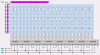
I found a neat little display board lying around in the shed which I got from an old Bandit/Fruit machine. It was probably used to create moving pictures as you regularly see on bandits.

It has 3 rows of 12 (36!) dot matrix LED Displays on it. Each LED Display has 5 x 7 LED's segments on it (that's 35 LED's each!) :) The part number written on each LED Display is LTP757R, Also on this PCB are 15 IC's, 21 Transistors, and a load of resistors. There appears to be no micro controller on the board. The PCB has 1 connector/Interface, The connector has only 9 pins.

Now my question is probably one you'll laugh at but I grabbed this sometime ago thinking it might be of some use but to be hoonest although it looks to be a useful little gadget I can't think of a use for it, nor for the life of me can I even begin to think of a way to 'drive' it.

Has anyone got any idea's on what I could use it for? Novelty idea's are welcome.... If I could make it say "Merry Christmas" then change to say "Happy New Year" or something silly, Just so I can put it to some sort of use as a Xmas decoration if nothing else!

I'll be amazed if someone can come up with an idea and a simple enough driver to get this display functioning!

hackableFM..... :D

***EDIT*** Other markings on the PCB are "SP.ACE MATRIX DISPLAY BOARD" and ""VERSION 2 REVISION A"
 
Last edited:
These Boards were originally manufactured for Ace Coin operated machines in the UK. Though I now believe the company is now part of the JPM group I will do some further research for you as a few years ago I used to work for ACE in their manufacture and servicing workshops in Birmingham.

In the meantime you may be able to get some information from this forum

**broken link removed**
 
Nice one, some info would be much appreciated.

:D FM...
 
The ICs probably only there to interface with a microcontroller or CPU on the main board. I wouldn't think it'd do anything, if you just connected it up to a power supply.
 
Hero999 said:
The ICs probably only there to interface with a microcontroller or CPU on the main board. I wouldn't think it'd do anything, if you just connected it up to a power supply.

Interface, Thats the word I was looking for when I made the original post. You are right in what you say in that it needs a microprocessor to control it through the inbuilt interface.

FM...
 
Hi again I can't seem to find much it would seem that if you knew the name of the original machine that it came out of then the type of control electronics (e.g. Space 2000, Mach 2000 etc (Chassis type)) could be identified. Then you could possibly acquire a schematic of the display section.

Did you try the other forum? Possibly a member could give you some information from photos of the board.
 
Unfortunately I have absolutely no idea what machine it came out of. I ripped it out of a machine I saw lying in a scrap yard! and this was some time ago so I have no chance of finding out now...

Never mind.... I'll rip it to bits and use it for something else!

FM...

I've attached a picture of it here anyway.
 

Attachments

  • untitled.JPG
    untitled.JPG
    172.5 KB · Views: 974
Hi. Basically what you have is a 21x60 dot matrix display. This could be an oscilloscope//analyzer display; a rough graphics display (think smiley faces bouncing around between display borders); a three line textual display with special characters, scrolling left-right, right-left, top-bottom, etc.; or anything you can visualize. I wouldn't be too quick to junk this, as it lends itself to many interesting projects.

This is 21 rows by 60 columns (or you can put it on its side and treat it as the other way). Let's say for argument's sake that the present orientation in your photo is "right side up".

The UCN5821A ICs along the bottom are serial-to-parallel latched LED drivers. That's why you can controll all this with just nine pins. The 60 bits needed to light the columns is a stream of bits driven serially into the input pin of the chip closest to the connector. A few other pins control the clock, strobe and output pins of these chips. Each chip holds eight bits. Each output pin has a Darlington transistor with enough power to easily drive all the LEDs in each column. You can drive in 64 new bits while the old information, latched in in the previous operation, is still driving the LEDs. There's no flicker while you pump in the next message.

The extra four bits at the end of the stream probably drives the 74HC154 decoder IC at IC15. This chip takes four bits in and pulls one of sixteen outputs low. Which output this is depends on the binary weight of the input. So, an input of "0000", or "low/low/low/low", pulls output 0 (Q0?) low. Put in "1111" (fifteen) pulls output 15 (Q15?) low, etc. These16 lines could then be used to drive the transistors, which in turn drive the row LEDs.

The 74HC138 is a three-in//eight-out decoder. Since we need to drive 21 transistors to control all the rows, and the '154 only has 16 outputs, this probably drives the remaining five transistors. The trick is, are the inputs latched or are these three pins driven directly by three pins in the connector? Since I can't see the info on the ICs to the left, I can't say what they do or suggest any further operation on this board.
And of course all the resistors are current limiters for the LEDs.

I got all the info for the ICs using Google searches, like "UCN5821A data".

Theoretically, if you know microprocessors and lookup tables and programming, harnessing all this power would be easy. You would have to figure where all the connector pins go to the ICs and how they work.

Whatever you do, have fun doing it.
kenjj
 
You have interested in this thing even more now, My problem is that I am only just starting to dabble with PIC's, Most of what you said above went straight over my head. lol.

I am gonna keep this thing and maybe one day I'll learn enough to drive it somehow. Unless anyone has any examples of a circuit which might just drive it then it'll lay about in the shed for another year or two I think.

Thanks for the information, I was hoping you might come back and say it can be driven just like an LCD display because I am playing with one of those at the moment and I am just about confident that I can get that working.

FM.
 
Mmmm, one quick correction. I said all the resistors were for current limiting for the LEDs. Actually, that applies to the resistors running along the bottom of the displays. The resistors on the left edge are probably the base biasing resistors for the transistors.

I'd like to know what the four ICs are on the right. Having this info might give me a better idea how this works, which in turn may let me supply a basic "do-this, then this" guide to driving all this with a PIC, if that's even possible.

Later!
kenjj
 
Well since you put it that way lol.

Here's a more detailed picture.

And I'm keeping my fingers crossed.

Thanks.

FM.
 

Attachments

  • DSC00431.JPG
    DSC00431.JPG
    480.2 KB · Views: 1,130
The 74HCT4094 at IC3 is clear enough. The rest are indistinct. Zanes says there is (are?) 4526(s) there. Kindly give me the numbers off the ICs and identify which these are by the IC number, i.e., IC1 thru IC5. F'rinstance:
ICs 1,3, and 5 are hct4094, and IC2 and 4 are (HEF?, HCF?)4526.

The 4094s are, like the 8521As across the bottom, chips you load serially and then latch in the info in a parallel fashion. They lack the powerful outputs though, so that suggests that these are actually driving some (all the?) transistors. 'Depends on how many there are. Perhaps the HC154 is used for other things, but my bet is it's driving 16 transistors based on the last 4 bits in the 8521As. We have too many gates here just to drive LEDs. I wonder if this read switches and passed their bit values back to the processor?

Anyways, I notice three heavy traces at the 9 pin connector. These are probably ground, 5V for the ICs, and a slightly higher voltage (6 to 12V?) to power the LEDs. Whatever, whoever, with 21x60 LEDs at 10 to 15 mA each, you will have to provide some serious power to this puppy!

The plot thickens!
kenjj
 
IC1 = HCF4094BE
IC2 = MC14106BCP
IC3 = HCF4094BE
IC4 + 5 = MC14526BCP
IC 6 - 13 = UCN5821A
IC 14 = MM74HC138N
IC 15 = MM74HC154N

Fingers still crossed.

The plot thickens. pmsfl. You lot are nuts! but I think you're great.

FM.
 
74138: 3 to 8-line Decoder/Demultiplexer
74154: 4-Line to 16-Line Decoder/Demultiplexer

I think, not sure about my 4526 assessment, didn't see the 1 there.
 
Never fear, JJ's still here. I just have to stop and spend time working, eating and sleeping. Also, there's more to this display then meets the eye. We have a wealth of shifting-latching(-driving) ICs, and some decoders. You can overlap quite a bit between all these chip types. I'm still noodling this, but this will have to wait til Friday, my first day of the weekend. In the mean time, Hackable, it would help no end if you did a continuity check of where each pin on the connector went to at the ICs. You're going to find a lot of overlap between the UCN5821s, for instance, as the clock, strobe and OE pins will be driven on all these chips at once. If nothing else, find the power pins for each chip on their data sheet and track them to a pin on the connector.

In the mean time, for inquiring minds seeking enlightenment as to what all these chips do, here's data sheets for your perusal. Not all these sheets can be reached directly. You'll have to click other buttons or jump to other sites from the pages these take you to.

LTP757R - 0.7", 5x7 LED Dot Matrix Display
https://pdf1.alldatasheet.co.kr/datasheet-pdf/view/121977/ETC/LTP757R.html

14106 - 6 inverter gates
https://pdf1.alldatasheet.com/datasheet-pdf/view/11969/ONSEMI/MC14106BCP.html

14526 - Presettable 4-bit Down Counter
https://www.alldatasheet.com/datasheet-pdf/pdf/11983/ONSEMI/MC14526B.html

HCF4094BE - 8-stage Shift-and-Store Bus Register
https://www.alldatasheet.com/datasheet-pdf/pdf/22357/STMICROELECTRONICS/HCF4094BEY.html

UCN5821A - 8-Bit Serial-Input Latched Driver
**broken link removed**

MM74HC138N - 3-to-8 Line Decoder
https://www.fairchildsemi.com/ds/MM/MM74HC138.pdf

MM74HC154N - 4-to-16 Line Decoder
https://www.fairchildsemi.com/ds/MM/MM74HC154.pdf

No doubt there's enough data in these sheets for some clever boyo (it's St Patrick's Day here) to deduce how all this connects and works.

Later!
kenjj
 
Hey guys,

That hardware looks remarkably similar to some of the designs I've come up with these last couple years and as kenjj has suggested, I suspect "we" could come up with a full schematic with just a little bit more work.

oem-21x60-matrix-small-png.18040


I typically connect the output enable pins and the strobe pins together on all of the MIC5821 chips and drive them with the PWM output pin from the PIC. This provides a simple mechanism for strobing the MIC5821 shift register data onto the output pins and controlling the display brightness and it also allows me to multiplex the interface pins for use as row driver lines during display on time and as DAT lines to load the MIC5821 shift registers in parallel during the display off time. I doubt the manafacturer is doing that here and suspect that the MIC5821 chip DAT lines are daisy-chained. We'll need to determine how those MIC5821 chip lines are wired.

We also need to see if the HC138 and HC154 outputs are indeed connected to the row driver transistors and how the other few chips are connected to the HC138 and HC154 inputs.

All in all, that looks like a nice bit of hardware but if it's set up to scan 1 of 21 rows that's really a pretty low duty cycle and so it means you may need a rather hefty power supply to provide the 'peak' current necessary to light up to 60 LEDs in a single row to decent brightness during a single row scan period.
 

Attachments

  • OEM 21x60 Matrix (small).PNG
    OEM 21x60 Matrix (small).PNG
    183.8 KB · Views: 3,142
Last edited:
Nice drawing, Mike.

Yes, at 10 - 15 mA per LED, that's 50mA or more per segment row, 600 or better for all of them. Those transistors don't look terribly beefy, but they probably only operate for 20 to 30 milliseconds (?) at a time, so no harm done. And you're not likely to operate all the LEDs in all segments (LED test, anyone? Fryyy-y-y!), and a character display will have an unused row and column of LEDs to deliniate the character, so 11 LEDs per segment go unused in this case. Still, plan on a one Amp supply, at least 500mA, just considering the displays.

The questions of the hour, for me, are A. do the 138 and 154 drive the row transistors, and, if so, which chips drive them? If not, we have C.: what the H* does drive the transistors?

Well, as for A. and B., we could always use the two 4-bit 4526 down counters. These are presettable. You can program a value into this that's suitable to drive drive the inputs on the 138 and 154 to "walk" through all the rows. Finish a row, clock the chip to subtract one from the output, load the column info, and keep going. When the last chip reaches zero, the "zero' output interrupts the processor to let it know, so the processor reloads the value. This could be tricky, as if you don't set these right, you'll be driving one line out of the 138 and 154 at the same time.

And then we come to C.
It's some combo of the last four pins of the last 5821 in the chain, the rest supplied by the outputs of the 4094s. The 4094 is another Serial-in//parallel-out shift register. Just hook the serial-out of the last 5821 to serial-in of a 4094 and keep pumping bits until you have the three bits for the 138. Connect this to the 5821s' common clock//strobe//OE pins and it's just more of the same serial data shifting. Introduce a single on-bit at the tail end of the 5821 pins, thus turning on the first row. When done displaying row one, pump in an off-bit and push the on-bit to row position two, turning on row two. Every time you finish a row, pump in another off-bit to push the on-bit one more position and light the next row. Continue until you have lit up TWENTY ROWS! Aye, laddy, there's the rub. We only have 20 pins available if we drive the transistors from shifter pins instead of the 138 and 154, which give us 24. Then again, as I said earlier, if you're doing 4x6 characters inside a 5x7 segment, then you always have a wasted row, so only need 20 rows. Of course, there are TWENTY ONE TRANSISTORS, so that's shot.
But, you only need seven lines to control the 138 and 154, so you really only need one 4094 to do the job. And the other 4094 does... ?

Problem is, every solution leaves a couple of chips on the board with no discernable purpose. And the 40106, a hex inverter chip, has no place (so far) in any of these schemes. It may be there to invert the clock or a control line.

*sigh*

Well, break's over, back to the grind.
kenjj
 
OK, I've finally managed to find an hour in which to do some investigating...

Here's what I have found so far.

The 9pin connector at the edge of the board appears to have 4 'data' lines, and connections for a dual power supply.

The wiring I have found are as follows.

Edge Connector pin 1 - pin 15 of IC2

Edge Connector pin 2 - pin 11 of IC2

Edge Connector pin 3 - pin 5 of IC2

Edge Connector pin 4 - pin 3 of IC2

Edge Connector pins 5 & 6 - Vss

Edge Connector pin 7 - Vdd to all chips, I assume this will probably be a regulated 5v supply.

Edge Connector pins 8 & 9 - this appears to be a power rail fed to the 21 Transistors which gets switched to the rows of leds as controlled by the rest of the circuit.

The Data in & data out of the UCN5821A's appear to be wired like a daisychain, In to out and in to out and in to out etc etc, (In at IC13 out to input of IC12, out of IC12 to input of IC11 and so on.). Also pins 6 are all linked on these UCN5821's and pin 7 are all linked. I assume this is as per the diagram posted by Mike,K8LH

The 21 'row power' transistors are driven by two IC's as follows. MC74HC154 pins 1-11 & 13-17 AND MC74HC138 pins 11-15. each pin via a 680:eek:hm: resistor.


So, The IC's have a seperate power rail. It looks like the LED's also have their own power rail dedicated to them, This power rail is switched to the rows of 60 LED's by a transistor which in turn is controlled by a pin from either the MC74HC154 or the MC74HC138. The colums however appear to be controlled from the UCN5821A's and I assume these chips sink the current which is limited by 1 of 60 x 680:eek:hm: resistors.

IC1, HCF4094BE appears to receive the data from the boards connector and pass this on to the two chips controlling the 'rows' & 'columns'.

I am as yet unsure what the purpose of IC's 2, 3, 4, & 5 are. Has anyone any further suggestions on where I should check next?

Transistors are TIPP116's, Darlington pairs.

hackableFM.
 
Last edited:
Could you list the IC number and IC type? I can't make out the IC type from the picture.

IC1 -
IC2 -
IC3 -
etc...
 
Status
Not open for further replies.

Latest threads

New Articles From Microcontroller Tips

Back
Top