Continue to Site

Welcome to our site!

Electro Tech is an online community (with over 170,000 members) who enjoy talking about and building electronic circuits, projects and gadgets. To participate you need to register. Registration is free. Click here to register now.

  • Welcome to our site! Electro Tech is an online community (with over 170,000 members) who enjoy talking about and building electronic circuits, projects and gadgets. To participate you need to register. Registration is free. Click here to register now.

Help with Thermister safety protection for Mosfet.

Status
Not open for further replies.

gary350

Well-Known Member
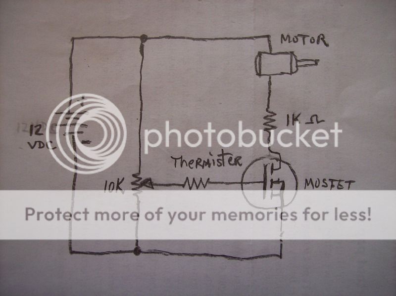
I found this circuit online variable speed motor control. I want to use this circuit for hobby model airplane fuel pump for a jet engine. The RC servo will turn the 10K variable resistor to throttle the engine. The original circuit has no thermister so I added one. I need mosfet over heat safery pertection. I have no experienc with thermisters I assume I need 0 ohms at 100 degrees and about 500 ohms at 140 degrees F. I hope I can use STP55NF06 I already have some of those. Mosfet max temperature is 150 degrees. Is that possible for a thermister?


007_zpsgmojvdb6.jpg
 
The thermistor will have no effect.
Do you have a heat sink on the transistor? (MOSFET)
We are short on information. What motor. How much current? What voltage?
What type of thermistor? (+) or (-)
 
A MOSFET has a very high input impedance so a resistor in series with the gate, as you show, will have little effect on the MOSFET current.
A typical thermistor has a negative temperature coefficient (resistance goes down with an increase in temperature) so, to reduce the MOSFET current with an increase in temperature you could place the thermistor from the MOSFET gate to source with a series resistor of the appropriate value from the gate to the pot wiper.
Pick a value for the series resistor so that the gate voltage significantly drops at the thermistor resistance for the maximum temperature of interest.

I assume that maximum MOSFET temperature is given in degrees Celsius(?).

Where will you measure this temperature?
 
google "protected Mosfets". They have internal thermal disconnect, among many other features and protections.
In the past I've used devices from STMicro, but nowadays many companies produce them.
 
Last edited:
The motor in the 12 vdc circuit is 12 vdc too. I have not checked the current yet because I dont have one to check. It is a typically model airplane fuel tank fuel pump. It is a tiny positive displacement pump about the size of a C battery.

I build this circuit on the work bench using small toy motor. The circuit does not work very well but I think I can make it work better. The 10k resistor is too sensitive. I think there should be a 240 ohm resistor in the gate circuit. I have a heat sink and will also have one in the airplane. I dont expect current to be very high on the motor, maybe the thermister is not needed, have to wait and see. The circuit will be closed up inside the fuselage so maybe an air vent hole will be in order.

PST_zpss9u7ketc.png
 
Heat: Lets say the motor was a short. This is is the worst case for heat. If the MOSFET was a short (closed) then the full 12V will be across the 1k resistor. 12V, 1k, 12mA, 144mW. The worst case for the MOSFET is when it has 1/2 the voltage across it. so 6V across the 1k, 6V across the MOSFET and 6mA and 36mw on the resistor and 36mw on the MOSFET. So there is not much heat here.

Maybe the 1k is wrong. 12mA is not much for a motor.
007_zpsgmojvdb6.jpg
 
Heat: Lets say the motor was a short. This is is the worst case for heat. If the MOSFET was a short (closed) then the full 12V will be across the 1k resistor. 12V, 1k, 12mA, 144mW. The worst case for the MOSFET is when it has 1/2 the voltage across it. so 6V across the 1k, 6V across the MOSFET and 6mA and 36mw on the resistor and 36mw on the MOSFET. So there is not much heat here.

Maybe the 1k is wrong. 12mA is not much for a motor.

You are right. I copied this circuit online, built it but didnt give it much thought. Looks like the 1k resistor is not needed. Motor amps r probably no more than 1 amp. If the motor were to lock up there would be 2 amps on the mosfet from AA alkaline batteries. Some rechargable batteries will put out 30 amps. Airplane will only have about 5 minutes of fuel. I may want to fly 7 or 8 times. I am thinking I will use rechargable AA batteries to save weight and they need to last for 8 flights. If the fuel pump dies the Receiver/servo batteries will still land the airplane. I dont want to recharge batteries to fly again and I dont want to carry 15 lbs of batteries around all day.
 
Last edited:
Motor amps r probably no more than 1 amp.
1A is more realistic than 12mA for a pump motor. But even if the running current were, say, only 500mA the FET might still have to dissipate ~ 3W so it would get very hot without a substantial heatsink. A lighter-weight solution would be an off-the-shelf speed controller, which responds to servo control signals and works by PWM.
 
This circuit works perfect. Volt meter shows the mosfet turns on at 2v and is full on at 8v. It is educational to see how it works. If I am careful I can get the motor to run slow about 20 RPMs.

019_zpsuuufemut.jpg
 
You should have a reverse-biased diode connected across the motor (i.e. from +9V to the FET drain, pin 2 in your drawing). Without it your FET may be killed by a back-emf voltage spike (due to inductance) if the motor current stops or becomes intermittent (e.g. due to poor brush/commutator contact).
 
Status
Not open for further replies.

Latest threads

Back
Top