Electro Tech is an online community (with over 170,000 members) who enjoy talking about and building electronic circuits, projects and gadgets. To participate you need to register. Registration is free. Click here to register now.
Welcome to our site! Electro Tech is an online community (with over 170,000 members) who enjoy talking about and building electronic circuits, projects and gadgets. To participate you need to register. Registration is free. Click here to register now.
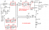
Hi, I'd like to ask if the schematic below will work. It is an IR and ultrasonic transmitter. I'd like to transmit the IR and ultrasonic differently that's why I connected it with different transmit pins. Can you help me please. Thanks.
MC14093 is a Quad 2-Input NAND Schmitt Trigger. Actually. I've made a circuit similar to this and it work. But it was for transmitting the US and IR signals at the same time. I modified the schematic and add another MC14093 so I can transmit the two signals in different occassion. Please help me.
It's difficult to say if the oscillator part will work, where are you
gonna find a 40 kHz crystal, or is it some kind of resonator ?
The - 3 dB point of the low-pass filter with the 100 k resistor and
the 50 pF capacitor is only about 32 kHz.
Only one comment, the output to the ultrasonic TX won't be of much
use because these transducers require a substantial amount of drive.
Remove both 220R resistors and replace them with the same drive
circuit driven by the previous "inverter" to form an H-bridge.
If you can't find a 40 kHz crystal you can always replace the
oscillator part with the following "no tune" circuit.
**broken link removed**
on1aag.
The oscillator part will not work because you used a nand gate
with a schmitt-trigger input and this kind of oscillator requires
the gate to operate in linear mode !
A 4011 will be a better choice for the oscillator part.
@on1aag: Thanks for your comment. I already tried a similar circuit. The same oscillator part and the same IR and US transmitter part. The only difference is the part to trigger the US and IR, where I only have one 2-input nand schmitt trigger connected to one pin for transmitting the two signals at the same time. And it work. Here's the previous schematic design.
This site uses cookies to help personalise content, tailor your experience and to keep you logged in if you register.
By continuing to use this site, you are consenting to our use of cookies.