Continue to Site

Welcome to our site!

Electro Tech is an online community (with over 170,000 members) who enjoy talking about and building electronic circuits, projects and gadgets. To participate you need to register. Registration is free. Click here to register now.

  • Welcome to our site! Electro Tech is an online community (with over 170,000 members) who enjoy talking about and building electronic circuits, projects and gadgets. To participate you need to register. Registration is free. Click here to register now.

Help with Schematic

Status
Not open for further replies.

bryan1

Well-Known Member
Hiya peoples,
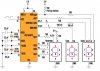
Below is a schematic that isn't to clear and I've spent a bit of time to no avail trying to decifer it. Where I'm having the problem is with the 7 segment pinouts. If anyone can redraw this for me in a simpler fashion so I can see where each pin goes from the pic I'll greatly appreciate it.

cheers Bryan1 :D
 

Attachments

  • schematic_110.jpg
    schematic_110.jpg
    77.5 KB · Views: 477
Maybe this helps: Anywhere there is a colon ( this symbol : ) it means that all numbers are included between. For example, the phrase b2:b6 means all numbers, b2, b3, b4, b5, b6. When they add a comma and another number, it means this : b2:b6,b9 = b2, b3, b4, b5, b6, b9.

This is done to save writting ( and drawing ) all the connections identified.

This is common practice in schematics, to save alot of redundant lines that connect everywhere, or are connected to alot of common elements. For example, if you had a data bus 64 connections wide, you would draw a single line, and label it something like D1:D64. This makes the schematic far cleaner, and ( supposedly ) easier to read.

In your case, the LED connections are shown with a single wire, representing several connections, as in chip pins # RA0:RA3,RA5 ( representing RA0, RA1, RA2 RA3, RA5 ) are, pin numbers 2:5,7 ( pins 2,3,4,5,7 ) connect to the LED segments a:d,f ( a, b, c, d, f )

This way, one line on the drawing, three labels, all meaning 5 wires. It saves clutter.

Hope this helps.
 
Hiya's,
Sorry I forgot to include the link to the circuit which is **broken link removed**
The project is for a low frequency tacho which I intent to use so I can record what speed my wind genny I just made will be. I guess the 7 segments are multiplexed but thats only a guess.

Cheers Bryan1 :D
 
thanks Zevon8 , good explaination. :)
Bryan , theyre not multiplexed..
on the units digit ;
RA0 --> a
RA1 --> b
RA2 -->c
RA3 --> d
RA5 --> f
RB7 -> g
Vcc -> e through a 150ohm resistor.

Tens digit:
RB0 ->a
RB1 ->b
Rb2 ->c
Rb3 -> d
RB4 -> e
RB5 -> f
RB6 -> g

Hundreds digit;
RC7 -> a,d e
RC6 -> g
RC5 -> f
RC4 -> c
5V -> b
 
Status
Not open for further replies.

Latest threads

New Articles From Microcontroller Tips

Back
Top