Continue to Site

Welcome to our site!

Electro Tech is an online community (with over 170,000 members) who enjoy talking about and building electronic circuits, projects and gadgets. To participate you need to register. Registration is free. Click here to register now.

  • Welcome to our site! Electro Tech is an online community (with over 170,000 members) who enjoy talking about and building electronic circuits, projects and gadgets. To participate you need to register. Registration is free. Click here to register now.

Help with pulse generator

Status
Not open for further replies.

John3

New Member
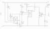
I want to build a pulse generator capable of driving a diode array – it needs to cope with the following output criteria 3.5v, 1khz – 10khz, 0.8A – 8A.
I have built the circuit in the attached diagram and it works well when driven by an input voltage of 6.5 volts. I need help making the following changes:

1. I need to drop the output voltage to 3.5V p-p – this need to remain constant regardless of load which could be anything from 0.8A all the way up to 8A.

2. I need some ideas to improve the stability of the circuit – under load when I was adjusting the frequency via VR1 the chips blew. I think this could be achieved by adding some transient voltage suppressors however I don’t know how to do that.

Any help would be greatly appreciated!
 

Attachments

  • PG_Scem_2.jpg
    PG_Scem_2.jpg
    366.5 KB · Views: 194
What is the load?

555s will not run reliably at ~3V. Get a CMOS version of the 555.

Are you trying to PWM the load. If so, the usual way of doing it is to maintain a constant frequency, but vary the pulse width. You seem to be doing the opposite?
 
Your 555 wiring setup looks very strange to me.???
I would not call this a very efficent way to use the 555.

Pin3 of a 555 is the output and i would have thought you would use that to generate the for the pulse, it would also pay to have a 103 cap to ground off pin5.
Reset pin floating.........that cant be good
No cap on the threshold pin6 is a bit strange and fail to see how you get any frequency control.

Hmmm think you should google for a better 555 circuit, there must be many.


Pete
 
Last edited:
I see a more conventional 555 set up in this thread and you might like a look.
You don't understand that the OP's circuit uses Pulse-Width-Modulation to efficiently adjust the average power to the load from almost nothing to full blast. It also has an adjustable frequency that is set only one time then is never changed again.
 
Hi MikeML,

The load is a diode array between 50 - 500 diodes. Current draw from 0.8A to 8A. I want a constant duty cycly of 50% however VR2 provides the PWM and frequency is controlled by VR1 and C1. Thus the circuit is fully adjustable PWM & frequency.

Thanks for your great suggestion to get a cmos version of the 555! I will see if I can find something on google (or can you suggest a chip?).

Hi SABorn,
I’m new to all this so I don’t know if the is the most efficient way to do this however I have built this circuit and it works well at voltages above 5V – see attached picture. If you zoom in on my scope you will see a p-p voltage of 6.43V and 558Hz output.
 

Attachments

  • Pulse Gen Pix_03.jpg
    Pulse Gen Pix_03.jpg
    77.8 KB · Views: 150
Sorry for the missunderstanding of your circuit.

At least tie the reset pin to V+ and not leave it floating.
I would still have a 0.01uf cap on the voltage control pin as well.

Pete.
 
You will need to replace the TIP 142 with something else if you are going to run at 3.3 volts. the 2.2 k and the lm393 won't drive it at 8 amps even now. You might be able to use a logic level Mosfet.
When it failed what chips blew?
 
It is a laser array each laser has a current draw of about 16mA
Ok so I can asume thay are 3.5v forward voltage? but if thay are diodes do thay need curent limiting? Andy
 
Everything I know about laser diodes is that you cannot just drive them from a fixed voltage, meaning you cannot just wire dozens of them in parallel. Do you have a data sheet for the devices you are trying to drive. If so, post it (or a link to it).
 
no probs SABorn - and thanks for your suggestions.

Hi ronv,
Thanks for your help - can you please suggest a particular mosfet? I am quite new to electronics. NB: this circuit was originally designed for an IRF740 mosfet however the designer suggested that if you want to run it at lower voltages that you could use a TIP142.
 
Hi MikeML,

You can indeed wire laser diodes in Parallel and drive them from a fixed DC source – I have done it many times. See link below for a data sheet:
**broken link removed**
 
Hi MikeML,

You can indeed wire laser diodes in Parallel and drive them from a fixed DC source – I have done it many times. See link below for a data sheet:
**broken link removed**

hi John,
That type is potted and has an inbuilt controller for the lasing diode, so it can be connected in parallel, the problem is some controllers have a 'soft' start so pulsing is not an option

A basic laser diode should not be connected in parallel with other diodes.

Eric
 
Hi Andy,

Sorry I missed your post. This generator will need to drive 50 to 500 of thise diodes thus a current draw of 0.8 - 8A. I am certainly interesed in adding circuit protection however don't know how (am out of my depth) do you have any suggestions?
 
Even though the TIP is a darlington at 3.5 volts the circuit can't drive it because of the Vbe drop and the Vce drop at 8 amps is also to high.
Use a logic level FET like IRLIZ34GPbF available at Mouser, Reduce R3 to 560 ohms to get more gate drive.
Change to LMC555 for the low voltage operation.
Tie reset to Vcc
Bypass control voltage (not to important with the CMOS 555.
I would change D1 to a schottky diode like MBRS340.
I think I would also bypass the power supply with something like 470UF electrolytic and a .01 ceramic cap.
 
Thanks heaps ronv (and Mike)!

That sounds like it will do the trick! Unfortunately my local electronics shop didn't have the mosfet in stock so I will have to wait about 5 days before I can make these modifications. Will let you know how I get on.

Thanks again!
 
Status
Not open for further replies.

New Articles From Microcontroller Tips

Back
Top