Continue to Site

Welcome to our site!

Electro Tech is an online community (with over 170,000 members) who enjoy talking about and building electronic circuits, projects and gadgets. To participate you need to register. Registration is free. Click here to register now.

  • Welcome to our site! Electro Tech is an online community (with over 170,000 members) who enjoy talking about and building electronic circuits, projects and gadgets. To participate you need to register. Registration is free. Click here to register now.

Help with power resetting problem

Status
Not open for further replies.

vandyo

New Member
I'm not the sharpest tack in the box on this stuff so any help appreciated.
At 70+ years there must be a lot of shorts upstairs.

In running a pair of CMOS 555s in a door alarm with a wall wart and battery backup, is there anyway to prevent the circuit from resetting when the power is interrupted by pulling the jack out or unplugging the wart? The power transisition does work ok but must produce enough of a delay to cause the reset.

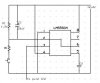
I am using LMC555CN in astable mode, pin 7 open and 2 & 6 tied to an RC network for a 15 sec delay for adults to move in and out the door without setting it off. It is wired "always on" and when needed is reset thru a switch driving 2 low. The 2nd IC gets its input from the output of the 1st.

The battery connections are wired direct to the jack's outputs. Pin1 shares the pos. with the wart & Pin3 gets the neg.

I also have tried using 2 steering diodes to direct the pos. but without success.
 
hi,
The 1st 555 you describe is wired as a monostable, thats the exit delay time and the 2nd I guess is the astable for the alarm.

I dont quite follow what you would like to circuit to do, is to not alarm when the mains power is repowered.?
 
hi Eric

I thought the timer was an astable. I said I was not too sharp on this. Yes the 2nd IC sets & monitors the protective loop but I am hesitant to say it is
an astable now. I will attempt to upload a graphic I have of the 1st IC once I figure out how to do it. My first attempt didn't work & I lost my reply. The pkg is a small door exit alarm I bought a while back and is for alerting adults that a small child has slipped outside un-noticed. It powers up into the delay & thet outputs to the 2nd one.The reset provides a 15 sec delay to allow adults to move thru the door without setting off the siren.

Since the delay happens on powerup after a power switch, it gives a child who may have pulled the plug from the jack a 15 sec window to get outside without setting off the alarm. I was looking for a way to stop that.

Thanks for your interest.

Timer.jpg (image)

Howard
 
Last edited:
I was just doing a search for this very same thing...although I don't have a solution just yet, but maybe this explanation will help to describe the situation for us both...

In a similar type of setup, a 555 is wired in the usual fashion (monostable), with the output pin 3 to an indicator LED and relay. As with the OP "vandyo", when power is turned ON, or interupted, even though the momentary input switch at pin 2 has not been closed (short to ground), the 555 will cycle and output to the LED and relay will occur.

The question is how to prevent the output on a power up or resumption of power condition when the trigger pin has not signalled that the event has really occurred.
 
Swap the position of C1 so that the 555 doesn't trigger on power up:
 

Attachments

  • Timer.jpg
    Timer.jpg
    24.8 KB · Views: 151
Last edited:
hi kchriste

Good suggestion i think but I'm not sure that would work for me. The board has to have a reset to restart it to allow a delay to let adults move in & out the door without setting off the siren. In the event of a pwr failure it also would not reset until someone pushed the switch. Will the switch function like that ? I hoping to find a way to make the board switch from wart pwr to bat pwr without resetting.

If I cannot do this, would it be possible to have 2 RC networks on this IC and have the one from the power change come up in say 1 sec, and have the reset action goto the 2nd one for the 15 sec. ?
 
In the diagram I drew, pin 3 of the 555 will stay near 0V when the circuit is powered up. When the button is pushed and released, pin 3 of the 555 will swing to near 12V for a set period of time determined by the RC time constant of R1 and C1 and then return to 0V.
 
hi kchriste

Sorry for not getting back with you sooner. I will admit I was a little unsure your suggestion would work. But I breadboarded the circuit and it worked fine. Thanks for the help. You have saved me some severe grinding of teeth.

I have a complete homemade proto board with the entire circuit so I will now modify it to make sure something else in the circuit is not affecting it adversely.

Thanks again. It will probably take me a few days to get to it, but once I finish I will msg the good news.

Howard
 
Isn't the modified circuit drawn by 'kchriste' (1-10-09 5:24pm) a 555 timer in astable mode? Is there a way to make a 555 in monostable mode not activate the output relay on a power on condition?
 
Isn't the modified circuit drawn by 'kchriste' (1-10-09 5:24pm) a 555 timer in astable mode? Is there a way to make a 555 in monostable mode not activate the output relay on a power on condition?

hi,
If you connect the RESET pin to +v via a 47K and the pin to 0V via a 100nF, that usually will hold off the 555 during power up.
 
Thanks Eric for the quick reply!
Sorry, just so I am clear: Are you saying to connect Reset pin #4 to +V thru a 47K resistor, AND also to connect the Reset pin #4 to 0 volts thru a 100nF cap? Normally I have the Reset pin #4 directly connected to +V unless a momentary switch is needed for an actual reset operation (by connecting pin #4 directly to 0 volts) .

I will try this later and post what happens, thanks!
 
Last edited:
Thanks Eric for the quick reply!
Sorry, just so I am clear: Are you saying to connect Reset pin #4 to +V thru a 47K resistor, AND also to connect the Reset pin #4 to 0 volts thru a 100nF cap? Normally I have the Reset pin #4 directly connected to +V unless a momentary switch is needed for an actual reset operation (by connecting pin #4 directly to 0 volts) .

I will try this later and post what happens, thanks!

Yes, it a Res to +V >> Cap to 0V and the junction to pin 4 RESET.

The higher the value of the Cap the longer the applied RESET.

You can also connect a n/o manual reset switch across the Cap, if required.
 
Isn't the modified circuit drawn by 'kchriste' (1-10-09 5:24pm) a 555 timer in astable mode? Is there a way to make a 555 in monostable mode not activate the output relay on a power on condition?
No, it is monostable. It works as per my quote below:
kchriste said:
In the diagram I drew, pin 3 of the 555 will stay near 0V when the circuit is powered up. When the button is pushed and released, pin 3 of the 555 will swing to near 12V for a set period of time determined by the RC time constant of R1 and C1 and then return to 0V.
The only disadvantage of my circuit is that the trigger input must charge the capacitor. This is fine when you have a manually operated push button switch or a source that can easily supply this current. It's advantage is that there is no extra capacitor required on the reset input (pin4) of the 555 and slow power supply rise times don't affect it.
 
Eric-Your modified reset pin 4 (resistor to +V, capacitor to 0V) worked like a charm, thanks!

kchriste-I couldn't get your modifications to work in my setup, but I will keep trying, thanks!
 
Status
Not open for further replies.

Latest threads

New Articles From Microcontroller Tips

Back
Top