I want build a "simple" :roll: security system which does the following:
A PIR triggers a VCR to start recording from a hidden IR camera.
The VCR is old and I was thinking of hard wiring a trigger circuit to the switches to avoid using a IR remote-control device.
There needs to be a timer so that once triggered the VCR will stop after 5-10min and then resets itself.
(Something like the diagram below.)
I've had look for a commercially available system, but it's looking like the best part of £200 :shock: Am I deluding myself to think that I could build a system for less?
I can quite happily solder use a soldering iron, but I haven't the first idea about chosing components and whilst I can get my head round designing systems, circuits themselves a way beyond me.
In other words, and I know this is really cheeky would someone like to do the design work for me
(BTW I'm expecting to source the parts form Maplin.)
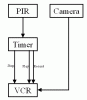