Continue to Site

Welcome to our site!

Electro Tech is an online community (with over 170,000 members) who enjoy talking about and building electronic circuits, projects and gadgets. To participate you need to register. Registration is free. Click here to register now.

  • Welcome to our site! Electro Tech is an online community (with over 170,000 members) who enjoy talking about and building electronic circuits, projects and gadgets. To participate you need to register. Registration is free. Click here to register now.

Help with My Year 11 Coursework

Status
Not open for further replies.

jo118

New Member
Hi I am making a sound sensitive disco light for my Year 11 Coursework project in Electronics.
We started working on the practical about 12 weeks ago and now there's only one week left
to finish it! After populating my PCB my teacher has been testing and fault finding my PCB for
over 3 weeks when I come in at dinner times 4 times a week. He is positive that there are no
faults left present in the PCB or in connections and is struggling to get my circuit working.

Here is my PCB mask:
**broken link removed**

Where there is a red line my teacher deliberately cut the track

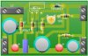
Here is where the components go (ignore the white test only read the black text):
**broken link removed**

(The block in the top right is a 2 way slide switch)
At outputs to LEDs I have used fly wires to connect LEDs placed within the circuit to conserve
PCB space and allow the LEDs to be in the correct position.

Here is the circuit design (the microphone has been replaced with and MP3 jack, he says he has
done that before and it worked):
**broken link removed**

My teacher says that the first transistor in the circuit is working (not sure about the second
and not sure how a PNP transistor works) and the third transistor on the right isn't. On the
third transistor more than 0.3v is going into it and it is constantly on.

In the left half of the circuit there are signs of the signal from the MP3 jack as the dial wobbles
while the music is playing.

Also, here is my Project so far. The casing is shaped like a Hedgehog and the LEDs will be the
spikes :)
**broken link removed**

Do you know why the circuit isn't working? Any help would be much appreciated.

-Josh
 
Last edited:
Check your PNP transistor. On one of the transistors the leads are cbe so the same should apply to all transistors if they are from the same manufacturer.
 
There is little that can go wrong here, except thetransistors. Triple check that they are correct in their orientation. Put the microphone back in, instaed of the speaker output, and test if it works with the original design.
 
Last edited:
Joshua,

I see you are using PCB Wizard. The circuit to pcb conversion database has
several errors. For example a transistor drawn in the diagram will convert
wrongly to the PCB. Attach your *.pcb files for both circuit diagram and PCB
layout and I'll take a look. Also little things like spacing between PCB pads
could be improved to prevent shorts, especially when etching your own boards.

The attached files are for a simple Monolithic PWM Boost Converter I use a lot.

sPuDd..
 

Attachments

  • LT1070cct.JPG
    LT1070cct.JPG
    35 KB · Views: 254
  • LT1070pcb.JPG
    LT1070pcb.JPG
    13.2 KB · Views: 325
@colin55: My Bad, When I made the PCB on PCB Wizard I didn't know which way to put in. On my actual PCB it is the other way round.
This is the best image I have of my PCB at the moment:
**broken link removed**

@bigkim100: I have abandoned the idea of including the speaker and just filled in the gap with a wire. Where the microphone would go is where I put the jack.

@sPuDd: I did not use the circuit to PCB converter, I made the PCB by hand.
In fact I didn't make the livewire circuit until after I made the PCB...
I've attached my PCB file as a zip

Thanks for all the input
- Josh
 

Attachments

  • year 11 project pcb new final.zip
    3.2 KB · Views: 189
I see that in the overlay the diode placement is incorrect, but it seems correct on the board.
Are you absolutely certain about the placement of the transistors?
 
Yeah, the diode was turned around so it has the correct orientation. I was going to mention this but I got frustrated because my posts had to be moderated before they appeared so I couldn't edit my post.
Also the top 2 pads of the switch are connected, I forgot to add it to the PCB mask. The switch is working fine and is on when testing.
The two NPN transistors are definitely the right way round.
EDIT: So on a PNP transistor it goes cbe on the flat side facing? And on the diagram and PCB the emitter is at the top. Then yes the PNP is the right way round.
The PCB itself was under etched, but I have scraped away all possible areas very deeply where there could be contact.
I have checked for loose connections and they are fine.
All the resistors and capacitors are the correct values and orientation and the transistors are the correct type.
LEDs are in parallel are all working, found when accidentally connecting areas by accident :p
The only problem with components so far is the 10k resistor smoked up and broke. I am certain that is the only component that was damaged. I replaced it. Any ideas why this happened?

So that's a summary of the components on my PCB. So any ideas what could be wrong? The transistors are the right way round. The LEDs should turn on when the signal of the mp3 player is high and turn off when it is low, so they should flash to the music. Currently they do nothing. But they do definitely work and look very pretty :)
 
Last edited:
How do the LEDs not require current limiting resistors. They are also different voltages and that will be a problem with the way they're wired.
 
They are different voltages?? How do you know? But true they could be. Four of them are a different type and are brighter. But at the moment there isn't enough voltage at the output track to light up any LEDs.
 
"Do not put LEDs in parallel with each other. Although this usually works, it is not reliable. LEDs become more conductive as they warm up, which may lead to unstable current distribution through paralleled LEDs. LEDs in parallel need their own individual dropping resistors. Series strings can be paralleled if each string has its own dropping resistor. "
Oh great lol.

But do you think this could be to do with why it's not working? Any chance that the LED's are causing too much resistance or something and the transistors are doing weird stuff with the current with their legs? I don't really know much about how transistors work but in a livewire simulation of the circuit, adding the speaker or even adding a volt meter alters the flow of current and even turns it the other way in some cases.
 
No-where have I seen a circuit diagram of the project. All I have seen is some terrible-looking PC board with jumpers crossing over each other and no overlay.

You would not last one day in my business with a layout like this.

<snip: spam link deleted>

The layout always matches the circuit diagram as much as possible to make identification and servicing easy. An overlay is also mandatory so that parts identification is simple.

Unless you follow a few basic rules you are left floundering all over the place, as is evidenced by the length of time this posting has been dribbling-about, trying to find a solution.

I lay down a simple set of rules and that’s how we have designed thousands of circuits, both for customers and for our magazine.

No-one has the slightest clue what you are designing or how the circuit is laid out.

Until you go back and start all over again, no-one can help you.
 
Last edited by a moderator:
Woooah I'm only 16.

But nevertheless I didn't provide a circuit diagram of what I actually did.
Here is my livewire circuit diagram (only difference is the LEDs have 3 rows):
**broken link removed**

Also i've attatched my livewire file
 

Attachments

  • sound detection circuit.zip
    2.6 KB · Views: 170
Let's step back a bit. Try lighting a single LED. Although 3V might be enough for some it will still require current limiting. Also the transistor will drop about 0.6v when on so your LEDs will only have about 2.4v available.
 
Where do you want me to start.

Firstly, we do not know the value of VR1 and 2. Assume they are 10k.

What is the purspose of R5. It is not needed.

You are not going to be able to illuminate the LEDs.

The reason is simple.

You will have to charge C4 to a value of 0.6v plus the voltage across a LED (approx 1.7v to 3v). The charging transistor will need to deliver a voltage 0.6v higher than this and although this can be done, it will take a long time to actually charge the 470u to a point where it will illuminate the LEDs via the emitter-follower transistor.

You need to change the output transistor to a common-emitter configuration and put a 10k between C4 and the base of Q3.

You then need to add current limiting resistors to the LED-strings.
 
Last edited:
@blueroomelectronics: How should I light a single LED? I have tried it with 1.5V straight through it but my teacher told me off because he said the current could damage it. But what is weird about these LEDs is you cannot light it by putting +V on the plus leg and -V on the minus leg. You have to put +V on plus and -V on both :S. But when doing this on a single LED they all light up. Actually I think the brighter ones light up slightly when doing plus and minus on the legs but when crossing the legs they light up fully and look very pretty.

@colin55: VR1 is 4.7K and VR2 is 47K
The purpose of R5? I don't know. I did not design the circuit. The original diagram is in my first post. So if I did the things mentioned at the bottom of your post should the circuit work? Thank you for your advice.
 
I have no idea if the circuit will work if you carry out the modifications because I don't know how the circuit will respond to a frequency of 1Hz.
The first thing you should do is increase the frequency so that you can at least illuminate one LED then add more LEDs and decrease the frequency.
 
Ooh heh I can't really increase the frequency. The signal comes from an MP3 player 3.5mm jack. So what goes in is what you get.
 
Status
Not open for further replies.

Latest threads

New Articles From Microcontroller Tips

Back
Top