Continue to Site

Welcome to our site!

Electro Tech is an online community (with over 170,000 members) who enjoy talking about and building electronic circuits, projects and gadgets. To participate you need to register. Registration is free. Click here to register now.

  • Welcome to our site! Electro Tech is an online community (with over 170,000 members) who enjoy talking about and building electronic circuits, projects and gadgets. To participate you need to register. Registration is free. Click here to register now.

Help with marine wiring

Status
Not open for further replies.

florida

New Member
It is common practice in the marine electronics world to tie all electronics accessories (lights, sonar, pump ect. ) to a common ground wire. That common ground then goes to the negative post of a marine battery. My question is, How do I splice the negative lead of accessories to a common ground wire? That would be like connecting three wires together. To further complicate things its common to avoid soldering because of the excessive vibration of the marine world. How should I connect accessories to a common ground?

My boat looks like this
**broken link removed**

Thanks for the help
 
If you are planning on paralleling several devices and circuits to a common ground cable and then routing a single conductor to the battery ground terminal without soldering, I would suggest purchasing a terminal block and crimp terminal connectors, the eye-hole style would be best. Terminal blocks usually have multiple connection points, but these can be made common to each other with jumper wires.

**broken link removed**

Some considerations. Make sure the common cable that is your "return path" to ground for all the circuits is of sufficient gauge to handle the amperage of all the circuits in sum, PLUS a bit of headroom. This is for multiple reasons. First, you do not want any added wire resistance that will cause overheating and potentially a fire. Secondly, long runs of ground wire will cause ground loops and can cause strange circuit behavior. Adequate wire gauge can minimize the opportunity for this.

Consider that your terminal block connections will be exposed to harsher conditions (possible saltwater?) and also vibration. A lock washer might be a good idea for each terminal...and a conservative bit of "Locktite" on the threads of the terminal screws may prevent a loose connection. Be careful, I'm not sure how conductive or insulative Locktite is but I use it conservatively with no problems. After connections are securely made, sealing your terminal block with silicon or in a protective box might not be a bad idea to prevent corrosion.

Also, it is not uncommon to fuse the ground wire that acts as your return path. Calculate the wire gauge and the parallel current of all your circuits under normal conditions. A good rule of thumb is to fuse for 10% above the expected operating current with a slow blow fuse. This will protect your ground cable from overheating and overloading.
 
You should be able to find gold plated terminal blocks for only a few dollars more than regular ones. That will help with corrosion issues. You may also be able to find enclosed PVC electrical boxes at home stores that have rubber gaskets. You just use hot glue on the wires going in/out and then the whole setup is completely water proof then. Depends on what you're able to find and how much effort you want to put into it.
 
Thanks for the ideas. Im going to go with the box idea,
There is simply nowhere on my boat to mount a premade switch panel. I am going to make one out of a PVC junction box with switches mounted on the outside. Here is a diagram I drew of my layout. Negative return wires from the accessories have been omitted for clarity. Is there anything blatantly wrong with this setup? It looks like I’m going to need 65 feet of 16 gauge wire. The boat is 15ft.

Thanks for the help


**broken link removed**
 
Hi florida,

your circuit seems to be OK.

For the cables I do not recommend to use hot glue. Hot glue crackles over a long period and won't make the connector box water tight anymore.

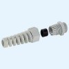
Here is a photo of cable "passages" with strain relief. They are also available without strain relief.

The two parts are conically shaped and press the rubber ring tightly around the cable, ensuring stablity of the connection.

Cable boxes fittet with those devices are IP66 (safety classification)

Boncuk
 

Attachments

  • BFMK_12.jpg
    BFMK_12.jpg
    5.2 KB · Views: 370
Have you calculated the total ampacity to come up with the 16 gauge wire? Just checking, as I don't know the total load you will be putting on the circuit. Remember, resistance on the ground cable "might" cause loop currents and potential noise, resistance, heat, etc. In other words, don't overlook this point.

Also, I noticed you didn't include a fuse per my suggestion on the ground bus. While not imperative I strongly encourage this minor addition for added protection. More and more commonly designers are using dual fuse protection in automotive electronics, especially where there is high power transfer like amplifiers and two-way amateur radios.
 
Will do, Dual fuse it is. Also the led lights dont come with amp ratings. I checked the literature and websight, any ideas? Thanks bankuk, sceadwian and ke5frf
 
Last edited:
Well, I don't know how intense they are, how many LEDs, how many lamps etc, but a round guess that they pull not much more than an amp would be close I'm sure. If you have an ammeter that can handle a few amps you may check it for yourself. If it has a peak hold indicator, use it to measure inrush as well as continuous current. Or, if the website provides a tech support phone number it may be worth the quarter for a phone call.
 
Status
Not open for further replies.

New Articles From Microcontroller Tips

Back
Top