Continue to Site

Welcome to our site!

Electro Tech is an online community (with over 170,000 members) who enjoy talking about and building electronic circuits, projects and gadgets. To participate you need to register. Registration is free. Click here to register now.

  • Welcome to our site! Electro Tech is an online community (with over 170,000 members) who enjoy talking about and building electronic circuits, projects and gadgets. To participate you need to register. Registration is free. Click here to register now.

Help with making LED's less bright!

Status
Not open for further replies.

stuwindsurf

New Member
Hope someone can help!

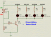
I'm fitting LED warning lights on my motorcycle to replace the existing standard bulb warning lights. I spoke to the tech guys at Maplin and they recomended their N**BY LED's 5mm super bright.

I have tried one with a 2W 100R resistor again as recomended and found them far too bright. I then bought some standard LED's which are not so bright but have coloured lenses.

I would like to use the super bright LED's as they all have clear lenses and wondered if I can use a bigger value resistor to cut the brightness down. The mcd of the standard LED's is 30mcd which is about right.

The spec for the super brights are:

Absolute maximum ratings: Ta = 25°C
Power dissipation: 130mW
Peak forward current: 100mA
Continuous forward current: 50mA
Derating factor: 0.4mA/°C
Reverse voltage: 5V
Operating temperature: -25 to +85°C
Storage temperature: -35 to +100°C
Soldering temperature: 260°C / 5secs
Absolute optical characteristics:
Ta = 25°C, If = 20mA, Vr = 5V
Symbol Min Typ Max
Forward voltage: Vf 2.3V 2.6V
Luminous Intensity: Iv 2500mcd 7200mcd
Dominant Wavelength: 625nm
Spectrum Radiation Bandwidth: 20nm
Reverse current: Ir 10µA
Viewing angle: 30°

Thanks in advance for any help with this!
Stu
 
Generally if the LED is too bright you can just add a larger resistor to dim it down. I also don't think you'll need such a larger power dissipation capabilty for the resistor. What's the supply voltage? 12V? You shouldn't be dissipating anywhere near 2W. A 1/4 W resistor should sufice.
 
Thanks for the reply.

Any idea what value resister I would need to use to get the brightness down to around the same as a standard LED, ie 30mcd?

Thanks, Stu

p.s the voltage is max 13.4v
 
Last edited:
Without the data sheet, I don't know the relationship between forward current and luminous intensity. I would just try out some different resistance values until you acheive the brightness you're looking for. I don't know if the relationship is linear or not. Maybe someone else knows.
 
hi Stu,
It may seem a bit like a sledge hammer to crack a nut type solution, but if you can't get the required brightness using a limiting resistor, a good 'variable' way would be to use a simple 555 timer circuit operating in astable mode, and using a trim potentiometer you can vary the intensity brightness to suite your needs.
Roy
 
How's the light spread on those?
One prob with LEDs, esp the 5mm ones, is that the spread may be too narrow and the taillight's outer lens surface may not be very effective at increasing the spread. This not only makes the center very bright, but the sides will be very dim.

The other problem is that the actual emitted area is very small. Looking straight into even a relatively low-power LED can be blinding even though the lumen output is not very high. If the LED were diffused through a clear frosted surface, the light is no longer blinding and it's not just because the light is spread out over a wider angle. It's because the brightness you see comes from a wider area, not a point.
 
Hi Stu,

I guess you won't be satisfied with dim instrument (warning) lights in bright sunshine.

Here's a simple circuit to dim the LEDs between 20 and 50mA. The LED current limiting resistors are calculated on the basis of UB=13.4V and the LED forward voltages (Uf) as given in the schematic.

Since the warning lights of the motorbyce may be wired a similar way as they are in cars you just have to open the ground connection and put the transistor between chassis (ground) and the LED cathodes.

Regards

Boncuk
 

Attachments

  • WARN-LIGHTS.gif
    WARN-LIGHTS.gif
    11.1 KB · Views: 494
How's the light spread on those?
One prob with LEDs, esp the 5mm ones, is that the spread may be too narrow and the taillight's outer lens surface may not be very effective at increasing the spread. This not only makes the center very bright, but the sides will be very dim.

Clear miss! :rolleyes:

The OP doesn't want to dim the tail lights, but the instrument panel warning lights. :)
 
At the risk of sounding crude, why not put a little piece of paper (etc) between the LED and the coloured bezel? Easy enough to adjust, needs no soldering etc.

I had an appliance that ran for years with a blob of blu-tak over the power light because it was one of those irritiating blue ones of ten zillion candela and yes you could still see the light was on even under the blu-tak. ;)
 
I guess you won't be satisfied with dim instrument (warning) lights in bright sunshine.

Here's a simple circuit to dim the LEDs between 20 and 50mA.


Thanks Boncuk

I appreciate the diagram. Each of my warning lights will have its own live feed, they are warning lights rather then instrument illumination lights, ie turn signal indicator, engine check light, high beam, etc so I'm not sure how I would need to change to diagram?

Stu
 
Last edited:
At the risk of sounding crude, why not put a little piece of paper (etc) between the LED and the coloured bezel? Easy enough to adjust, needs no soldering etc.

The LED's are sunk in to a Chrome handle bar clamp and protrude from the surface so unfortunately I can not put anything over the front of each LED to dim them down.
 
Hi Stu,

you just wire the LEDs like the lamps were wired with the exception of a current limiting resistor in the positive rail and an NPN-transistor in the ground rail.

All LEDs in the schematic are connected to +UB. Switches (like low/high beam switch) supply +UB for the control light. Just use that output for the control indicator LED and leave the cathode like it is in the schematic.

To dim the LEDs I suggest to use a sliding potentiometer mounted in a small metal enclosure (spray water tight). Using a slider you might use the thumb for convenient operation.

Boncuk
 
The max allowed continuous current for the LEDs (not in hot sunshine) is 50mA.
The "recommended" 100 ohm resistors provide a current of 110mA. Each resistor dissipates 1.2W.
 
Hi Stu,

you just wire the LEDs like the lamps were wired with the exception of a current limiting resistor in the positive rail and an NPN-transistor in the ground rail.

All LEDs in the schematic are connected to +UB. Switches (like low/high beam switch) supply +UB for the control light. Just use that output for the control indicator LED and leave the cathode like it is in the schematic.

To dim the LEDs I suggest to use a sliding potentiometer mounted in a small metal enclosure (spray water tight). Using a slider you might use the thumb for convenient operation.

Boncuk


Thanks again Boncuk
 
Status
Not open for further replies.

Latest threads

New Articles From Microcontroller Tips

Back
Top