Rajagopal87
New Member
I have a few doubts with the following circuit:
**broken link removed**
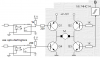
consider the one at the bottom without any inverter..
There are no protection diodes in the circuit!!
Is it ok to use this or Must the diodes be added? Is a 1n4007 across the four transistors will do?
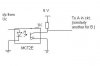
Also to connect its i/p to an at89c51 Uc, is the following modification ok(included in attachment)? Is 1K resistor ok?
Also what about the base terminal of the mct2e transistor? can it be left open? What about the NC pin? Can it be left open or must be tied to high or low?
Thank You.
**broken link removed**
consider the one at the bottom without any inverter..
There are no protection diodes in the circuit!!
Is it ok to use this or Must the diodes be added? Is a 1n4007 across the four transistors will do?
Also to connect its i/p to an at89c51 Uc, is the following modification ok(included in attachment)? Is 1K resistor ok?
Also what about the base terminal of the mct2e transistor? can it be left open? What about the NC pin? Can it be left open or must be tied to high or low?
Thank You.
Attachments
Last edited: