Continue to Site

Welcome to our site!

Electro Tech is an online community (with over 170,000 members) who enjoy talking about and building electronic circuits, projects and gadgets. To participate you need to register. Registration is free. Click here to register now.

  • Welcome to our site! Electro Tech is an online community (with over 170,000 members) who enjoy talking about and building electronic circuits, projects and gadgets. To participate you need to register. Registration is free. Click here to register now.

Help with LM2917 Frequency to Voltage Converter

Status
Not open for further replies.

crice

New Member
I posted a thread about a lower power anemometer here:
https://www.electro-tech-online.com/threads/low-power-analog-wind-sensor-anemometer.22595/?highlight=anemometer

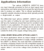
I followed the steps outlined in the Easter Egg Anemometer site, however I am having some trouble with the LM2917 Frequency to Voltage chip from National Semiconductor.

My circuit looks exactly like this:
**broken link removed**

All of my components are the same. However, I don't think that I am wiring up my AC frequency-in correctly. For my AC frequency, I want to use a reed switch / magnet to generate voltage pulses. Is this how I am supposed to wire up the reed switch (ASCII art time):

----- 2.5V
|
|
/
|
|---- LM2917 PIN1
|
----- GND

The "/" is my reed switch. When a magnet passes over the switch, the switch closes and current should flow through. When I hook it up like so, I get no reading from the LM2917. When I attach an external signal generator to PIN1, the LM2917 reads accurately. I believe that I am just doing the AC frequency-in incorrectly. I think that I should be putting a resistor between GND and PIN1, but I am not sure.

Any suggestions or tips will be greatly appreciated!
 
The 8-pins LM2907/LM2917 needs AC (voltage goes above and below ground) for its input. You are feeding it pulsed DC.
The 14-pins versions can have their reference input biased so that the input works with pulsed DC.
 

Attachments

  • LM2907-2917 notes.PNG
    LM2907-2917 notes.PNG
    36.8 KB · Views: 7,749
Audio, do you think his input frequency is high enough? Seems to me that if the signal is coming from a reed switch, it's gonna be pretty low frequency. If the frequency is suitable, couldn't he just capacitively couple the signal into the 2917?
JB
 
jbeng said:
Audio, do you think his input frequency is high enough? Seems to me that if the signal is coming from a reed switch, it's gonna be pretty low frequency.
It certainly will be a very low frequency. When the wind blows hard then the reed switch will not work fast enough or it will quickly wear out.
The LM2907/LM2917 can measure extremely low frequencies.

If the frequency is suitable, couldn't he just capacitively couple the signal into the 2917?
I think a coupling capacitor would get charged by the input protection diodes then won't work. It is designed for a very small AC signal caused by a magnet spinning past a coil.
 
Thanks for your input. I will try to get the 14 pin version soon.

I am curious, did I wire the reed switch correctly? When the switch closes, doesn't the current go straight to ground? How does the LM2917 pick up the signal?
 
crice said:
I am curious, did I wire the reed switch correctly? When the switch closes, doesn't the current go straight to ground? How does the LM2917 pick up the signal?
It was very difficult to read your terrible ASCII schematic but it looks like you shorted the signal to ground so it won't work. The input of the LM2917 needs a resistor to ground.

Instead of the reed switch, why not spin a magnet past a coil? Then the coil can feed directly to the IC you have now.
 
I'm not sure what you mean by spinning a magnet past a coil?

I'm sorry about my ASCII art, but you don't have to insult it.
 
crice said:
I'm not sure what you mean by spinning a magnet past a coil?
I am also not sure. The datasheet says to use "a magnetic variable reluctance pickup". Look it up in Google.

I'm sorry about my ASCII art, but you don't have to insult it.
Of course I will insult terrible schematics like yours. This is year 2006 isn't it?
My schematics are made clearly by using Microsoft's Paint program.
 
audioguru said:
The datasheet says to use "a magnetic variable reluctance pickup".
That type of pickup would probably have been my choice anyway. They are easy to make, and if you bring the sensing end of it near a small, rotating steel gear, you get n waves per revolution, where n equals the number of teeth on the gear. Much better than one pulse per revolution, IMO. Take a look at this thread.
JB
 
I created my sensor from an old single platter hard drive motor. Hard drives with one platter have a thick spacer ring on the spindle motor. There is sufficent material to drill then tap this ring at 90 or 120 degree intervales for 6-32 machiens screw. Then a machine screw becomes each leg that hodls a cup. I use a four inch screw right now. (see further note below) Also to reduce rotor mass, you can leave the original platter retention ring off and use the legs as set screws to hold the ring in place. My cups are practice golf balls drilled through (smalled than needed as to make a snug fit) then cut in half. Drill before cutting. The dimpled ones are kind of a plastic storage container type of plastic, sort of flexible and not brittle like the eggs. My theory is it will stand up in use longer. I do not know if the dimples affect the linearity of the scale however.

I have mechanically tested this to ~70mph and it seems sturdy (nothing worked free durign a tweenty. It also provides an ac output that is linear to shaft speed (not tested with wind yet...just by spinning it on the workbench with very awkward leads clipped/pressed on). It begins spinning in the 7-8 mph range. This is with the cups on the very tips of the screws. By going with say a five inch screw I am certain the sensitivity would be increased. For high wind my gut feeling would be to go with a screw/rod long enough to go through the cup all the way.

i will try to post a picture of the waveform later on today. I apologise for the quality of the pics here, i only had a cameraphone :(

(pictures coming)
 
**broken link removed**

Closeup of hub showing layout, I will drill and tap for 4-40 screws later to help retain the sensor

**broken link removed**

Overview of the unit, note set screws to retain the sensor, these will squeeze a piece of sched 20 pvc spacer around the base of the hard drive motor

**broken link removed**

Cup detail, Screw should pass through cup for maximum durability. I plan to move to stainless all thread or threaded brass rods in the very near future (before I put it on the roof). This design does stay together at sustained 70 mph windspeed though.

**broken link removed**

Closeup of hub, spacer ring is drilled then threaded. If you do this use lots of cutting oil on the tap! You have no room for error due to the thiness of the ring. The fit of this ring to the spindle is snug enough that you will have to clean up the inside of it after drilling and tapping to make it fit.

**broken link removed**

There is a spacer ring that fits in here to make it a snugger fit

**broken link removed**

This is how it will mount, the direction indicator will go on top, by mounting it downward this way we eliminate most of the problem with water getting inside of the motor. The bearing is of such high quality that it doesnt care one way or the other.
 
Last edited:
Status
Not open for further replies.

Latest threads

New Articles From Microcontroller Tips

Back
Top