Electro Tech is an online community (with over 170,000 members) who enjoy talking about and building electronic circuits, projects and gadgets. To participate you need to register. Registration is free. Click here to register now.
Welcome to our site! Electro Tech is an online community (with over 170,000 members) who enjoy talking about and building electronic circuits, projects and gadgets. To participate you need to register. Registration is free. Click here to register now.
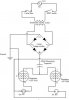
I need a little help building a dual regulated power supply that will output 5vDC and 12vDC. Please let me know if you see any problems with my circuit or a way to do it better as I am pretty new at this. Attached is a diagram.
Well, I've never seen such symbols for voltage regulators but
that's ok. Your schematic will not work because capacitor is
wired wrong. It should be accross bridge rectifier output.
It also should be 10-20 times bigger. Other than that everyhing is ok.
You could cascade regulators. This is specially prefered if
current draw on 12V is low but on 5V is high.
Some regulators really should have diode accross regulators input
and output to protect them. I guess it doesn't hurt to put them
anywhere.
Following should give you an idea.
The capacitor should come across rectifier's (+) output and ground. The I inputs of regulators should be directly fed from rectifiers output.
See modified schematic below.
This site uses cookies to help personalise content, tailor your experience and to keep you logged in if you register.
By continuing to use this site, you are consenting to our use of cookies.