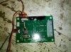
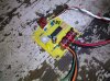
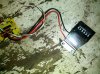
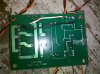
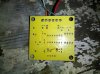
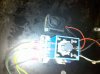
I am designing a circuit(s) for a game machine I want to build but I don't know how to approach it. I have attached the parts I have on hand that I can test with. I think these will suffice for the most part of the design. I intend to use them unless someone suggests there is a better method ie less time consuming, cost effective, etc.
Here's the plan:
1. A cash acceptor/machine takes in a bill and once the bill is verified, it triggers the blue relay (attached) for the main circuit to turn on for a period of max 15 seconds (which can be adjusted on the relay). Would like to activate main circuit with a START button after cash is inserted and accpeted.
2. On the main circuit there is an IR sensor. If anything breaks line of sight, it will trigger i) an alarm/siren (yay I won!) ii) trigger cash to be dispensed from cash dispenser that will be installed, and iii) turn off the main circuit so no more cash can be dispensed. basically if line of sight is broken within the 15 second interval, it turns itself off so there is no repeat loop of winning/dispensing cash.
If 15 second interval is reached without breaking line of sight, circuit turns off. (nothing complex here, relay will shut off circuit after 15 seconds).
3. need to attach a digital LCD or other small display that keeps count of the credits player has left. eg I put $5 and i have 5 credits. The main circuit is activated by a START button. Need to design something here where the counter keeps count of credits and allows player to reset the 15 second main circuit for each credit available.
4. When START button is activated, ie main circuit turned on, i need another relay to turn on an AC blower motor. just an AC relay that can handle at least 5-10 amps 120 V. Blower motor has to turn off when main circuit turns off either when line of sight of the IR sensor is broken or at the end of the 15 seconds.
5. Trigger a candy dispenser after game is played regardless if line of sight is broken or time is up.
These are the main objectives here. Anyone want to take a shot at it? If someone has any idea if this kind of design is pre made or can easily be built as a kit or something, please share. If anyone would like to contact me in private, please do so at gexamb@gmail.com.
Thanks for looking.
PS. i will try to draw some kind of diagram soon to be more clear.
Attachments
-
 IMG_20110131_185909.jpg1.5 MB · Views: 393
 -
 IMG_20110131_185921.jpg1.4 MB · Views: 448
 -
 IMG_20110131_185936.jpg1.4 MB · Views: 419
 -
 IMG_20110131_185950.jpg1.5 MB · Views: 425
 -
 IMG_20110131_190004.jpg1.3 MB · Views: 352
 -
 IMG_20110131_190031.jpg1.3 MB · Views: 391
 -
 2010-02-22 20.26.56.jpg1.1 MB · Views: 457
