Continue to Site

Welcome to our site!

Electro Tech is an online community (with over 170,000 members) who enjoy talking about and building electronic circuits, projects and gadgets. To participate you need to register. Registration is free. Click here to register now.

  • Welcome to our site! Electro Tech is an online community (with over 170,000 members) who enjoy talking about and building electronic circuits, projects and gadgets. To participate you need to register. Registration is free. Click here to register now.

Help with Coin-op design

Status
Not open for further replies.

bbwfw

New Member
I am trying to make my own coin op machines. I am new to electronics and this is a bit harder for me. The big problem I have is having a circuit timed to stop after turning on as well as accepting money. I had a friend make a schematic of one and I am not sure it will work I think he misunderstood me. I am looking to do a couple of different things. I was wondering if a momentary switch would work or one of those little push button type things and have the coin directed to fall on it or a attached thing to hit it to start. Then the other problem is time. The schematic he made should give me a set time but for some other ones I want to make I wondered if I could use a timer schematic from a 555 using a pot. and add to the rest of the schematic to make the thing work but for a certain duration when it was turned on.

So ultimatley I need to know:
1. How to get something falling to start the machine.
2. How to limit the machine to work for a short time.
3. Also once it is off to be able to start up again.

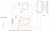
I have attached my schematic for a love tester machine my friend helped make it should have the time part solved but turning on and off from a coin he used a microswitch and not sure if that is right. If it is let me know. I still have some other things I want to make too which will need help with a timer of some kind.
 

Attachments

  • Macho_Meter_With_Coin-Op.png
    Macho_Meter_With_Coin-Op.png
    13.5 KB · Views: 272
At first glance it looks good. You get it to start by having a coin fall on the microswitch and quickly roll off. Your friend already pointed out R6 as where to adjust for time. It already stops by itself, and you restart it by dropping a coin on the microswitch.

2 things...9 volt batteries don't like driving 5 LEDs at once. You might want to put 2 or 3 in parallel. When you put a potentiometer in the R6 position, keep a "minimum time" resistor in place or you'll smoke the chip.
 
I was not going to use a battery I want this plugged into the wall. This schematic I am not worried about the timer part but some other ideas I am thinking of using a timer. Maybe I should ask for help on this schematic and then ask help on the other idea later. But you think this would then work with a microswtich to turn it on and then once it was one it would turn off after the time and then when another coin droped to start the microswitch it would og on again?

Thanks for the help by the way I really appreciate it.
 
Im kind of anal rententive about things so I like to verify to make sure, especially when it is something I am not as comfortable with and while I have been doing electronics for years its only been simple kit stuff so trying to work out my own designs is a bit trickeir. Thanks
 
I have been doing electronics for years its only been simple kit stuff

Why dont you use timer kits. That way you dont have to make Boards. Andy
 
1)2)3)google 555timer circuits, you need to use a one shot circuit to start it up and turn off after time(it will wait for NEXT)
THats what IC2 is doing in your friends circuit, adjusting R6 & C2 will change your "on" time line, there are lots of online calculators
 
Cool. I've always wanted to make things coin-operated.
I thought about using an infrared transmitter beam with a receiver and having the coin interrupt the beam to trigger the devise. Fancy.
But I like the thought of the shear weight and clunk of the coin doing it too. Fancy-shmancy can wait.
Does the IC3 thing work? It is an astable setup, right? I don't see a resistor between pin 6/2 and 7. Maybe it doesn't matter.
Also I see "Touch pads." Is this just using a part of the body to make the connection that makes IC3 operate? Does it work well?
Does using IC2 (555) as a power supply for 2 other chips work well? I've always tried to avoid that. But if it works - Fancy can wait on that too.
 
I remember a time when you could get the bill scanners for about $20.

DIY Quarter accepters were about the same. They used weight, conductivity, and magnets. If someone tries to use a "slug" (Fake quarter, or piece of metal the same size as a quarter, like a washer) in the coin slot, it would reject it if the tests didnt pass.

The coin drops onto a plate. The plate is connected with a shaft to a load cell a uC gets the weight and checks it for the proper weight tolerance.

There are electrodes (solder pads) on the plate that test for resistance/conductance.

A magnet is energized, if the coin lifts, you know its fake. You check for lift with the same weight scale. If the "quarter" gets lighter when the magnet is on, its fake.

A servo or solenoid can direct the coin, when dropped after testing, into a slide to the coin return, or the cash box.

Neat. And pretty easy with those stick on load sensors. The magnet was a nail with some copper wire wrapped around it.

Easy and cheap to do.

If you have a CNC machine, or access to one, you can make a professional or artistically done "face plate" for the coin op.

The same friend who made the above ones, had a few cut from plexiglass. REAL neat. With some etching and some LEDs, it was quite "inviting".

You WANTED to put your money into it. Kind of like an exotic dancers g-string. ;)
 
Very sophisticated, good info. I guess for mine I wouldn't care what they put in it, as long as it was round and thin. I make these mechanical sculptures and thought it would be neat to have people drop in a coin to make them go. If I got slugs, good on them for even bothering to give me a slug.

Also, I see you attached a photo to your post. I tried to attach a pic and it asked for a URL. I hate to bother YOU with this, but
Is that the only way to "attach" a photo? Can you tell me where the info on HOW to use this site is?
 
Status
Not open for further replies.

New Articles From Microcontroller Tips

Back
Top