Continue to Site

Welcome to our site!

Electro Tech is an online community (with over 170,000 members) who enjoy talking about and building electronic circuits, projects and gadgets. To participate you need to register. Registration is free. Click here to register now.

  • Welcome to our site! Electro Tech is an online community (with over 170,000 members) who enjoy talking about and building electronic circuits, projects and gadgets. To participate you need to register. Registration is free. Click here to register now.

Help with Code Lock on 16f88

Status
Not open for further replies.

Sig239

Member
I have succesfully ported over nigels tutorial 9_2 to a 16f88.
I'm using a 3x4 keypad instead of a 4x4 keypad.

The problem occurs when I try to use RB3 as an output to light an LED,
simulating actuation of a lock solenoid. I have commented out the two
lines in the scan routine which tests rb3 (column 4) for a high signal.

When I switch rb3 to an output, the LED flashes briefly after power is
applied, and no key presses are accepted. The LCD functions as
expected, displaying "Enter Code!."

I suspect, there is something I'm missing in the scan routine, but I'm
not sure.

Any help would be much appreciated.

I have included the source code that does not work.
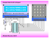
The hardware is wired the same as Nigels with the exception of an LED
and resistor going from rb3 to ground and nothing else on rb3. And a 3x4 keypad of course.

Find Tutorial 9
 

Attachments

  • tut9_2_16f88.asm
    10.6 KB · Views: 213
  • keypada[1].gif
    keypada[1].gif
    2.4 KB · Views: 287
  • board3[1].gif
    board3[1].gif
    3.1 KB · Views: 352
Please, someone must have some input. I've seen all the talented coders on here. It must be something simple that I'm missing. I can provide any other information needed. I have all the data sheets etc. I'm just not coming up with anything. I guess I'll go through the data sheets again. I was feeling quite pleased with myself for getting it ported over to the 16f88 without help :D
 
Your problem is that the code is still writing to RB3. You need to go through the code and change wherever RB3 is written to leave it alone, for example
Code:
Chk_Keys	movlw	0x00			;wait until no key pressed
		movwf	KEY_PORT		;set all output pins low
Needs to be,
Code:
Chk_Keys	movfw	KEY_PORT	;get port
		andlw	0b00001000	;keep RB3
		iorlw	0x00		;wait until no key pressed
		movwf	KEY_PORT	;set all output pins low
Note that in this case the iorlw does nothing but will be required where values other than zero are used.

Mike.
 
Hello Mike, thank you so much for responding. While I do see the folly (and potential future bugs) in writing to the pin, at this point in the program, writing a zero does not effect the outcome.

I've located the source of the problem though.

Code:
Chk_Keys        movlw    0x00              ;wait until no key pressed
 
;I know its bad to write to the pin, but its already low due to the lack of pullup.
                       movwf    KEY_PORT      ;set all output pins low
;After the movwf port b is b'00000111' (pullups on rb0-2)
                       movf      KEY_PORT, W
                       andlw     0x0F               ;mask off high byte
;masking the byte still results in b'00000111'
                       sublw     0x0F
;herein lies the problem, subtracting b'00000111' from b'00001111' (0x0f)
 results in b'00001000' and leaves the Zero flag cleared, thus sticking me in an
infinite loop when the next instruction skips "goto keys" and instead goes 
to a short delay and then back to Chk_Keys.
                       btfsc       STATUS, Z        ;test if any key pressed
                       goto       Keys                 ;if none, read keys
                       call        Delay20
                       goto      Chk_Keys          ;else try again

At some point though rb3 is going high because I see the LED flash once, before getting stuck in the loop. I don't see anywhere when rb3 is being writen high though. I guess I just have to fix one thing at a time, starting with any writes to rb3 :D I'll need to analyse the code you offered so I can understand how it changes the behavior of the routine. Any help you give is much appreciated. Thanks again
 
Oh yes, I see! I'll change that and the parts I found reading rb3 also. I won't be able to test the changes till tomorrow though.
 
The code I posted above simply leaves RB3 unchanged.

To fix the later code you can do,
Code:
Chk_Keys	movfw	KEY_PORT	;get port
		andlw	0b00001000	;keep RB3
		iorlw	0x00		;wait until no key pressed
		movwf	KEY_PORT	;set all output pins low
		movf	KEY_PORT, W
		andlw	[COLOR="Red"]0x07[/COLOR]		;mask off high byte
		sublw	[COLOR="red"]0x07[/COLOR]
		btfsc	STATUS,Z	;test if any key pressed
		goto	Keys		;if none, read keys

Mike.
 
Excellent, thats what I came up with too. Thank you sir.:D I "see" it better with binary though, so I changed it to b'00000111'. I'll try out the code tomorrow, and post it here if it works as planned.
 
I'm still working on the code a little at a time, but i have a question. If I perform a movwf, does w get erased or does it still contain a copy of the contents?

EDIT: Never mind, I googled and found that w is unaffected.
 
Last edited:
Well, I have code that works well now. I started to have too many changes to keep track of, so I started over with Nigels code.

One thing I learned from the data sheet is to clear the port latches when initializing the ports. Evidently the pin was starting out high when I made it an output.

Also, since it was meant to be in the locked mode until it was "told" to be unlocked, I decided to leave in any code that wrote a zero to the pin. Therefore, all I really had to do was change the scan routine. I saved the port to a temporary register and performed the rrf there instead of directly to the port. That allowed me to clear the lock pin before applying the changes to the port.

I created an "Unlock routine" which just consists of setting the lock pin high and returning. And a "Lock routine" which clears the lock pin. I call the unlock routine at the beginning of the correct code routine and call the lock routine at the end of it, so that while "correct code" is displayed, the lock solenoid is actuated.

If anyone is interested, I have attached the working code. Also, if anyone has questions on the specifics of porting it over to the16f88, just ask.
 

Attachments

  • tut9_2_16f88.asm
    11.1 KB · Views: 199
That's nice! Thanks for including the code. I haven't implemented the eeprom code storage yet. I like the keypress feedback also. Do you use it to lock anything?
 
I might have to use one of Mike, K8LH's handy multitasking code tricks to free up some pins for the feedback buzzer:D.
 
That's nice! Thanks for including the code. I haven't implemented the eeprom code storage yet. I like the keypress feedback also. Do you use it to lock anything?

No, it was just a 'learning' project. I had been thinking about making another as an actual lock, with the components under the actaul keypad (smd). Don't know if I'll get around to it for a while though.
 
No, it was just a 'learning' project. I had been thinking about making another as an actual lock, with the components under the actaul keypad (smd). Don't know if I'll get around to it for a while though.

Shouldn't the keypad be located away from the microcontroller and hence, the wires that actuate the lock solenoid? Someone could just pry the keypad off and actuate the lock without any code.

You can re-task the LCD D4..D7 lines to drive the keypad columns (or rows) to free up 4 pins...

Hi Mike, can you show me an example of this? I think I understand the software side, but I'm unsure how you would isolate the hardware. Thanks for your input.
 
Here's one of a hundred ways you might do it. Basically the LCD ignores data placed on the D4 through D7 lines and the RS line until you strobe the E line so you can borrow those lines to drive the columns or rows on your keypad in between writing to the LCD. The diodes prevent shorting out a high output to a low output if multiple keys in the same column are pressed at the same time. The diodes in this example are set up for sensing active low key presses using the internal PORTB pull-ups and requires setting only one of the column lines low at one time when scanning the keypad. If you look you should find plenty of examples like this on the 'net.

Happy Holidays, Mike

keypad-lcd-png.36530
 

Attachments

  • Keypad + LCD.PNG
    Keypad + LCD.PNG
    39 KB · Views: 1,120
Last edited:
Status
Not open for further replies.

Latest threads

New Articles From Microcontroller Tips

Back
Top