Continue to Site

Welcome to our site!

Electro Tech is an online community (with over 170,000 members) who enjoy talking about and building electronic circuits, projects and gadgets. To participate you need to register. Registration is free. Click here to register now.

  • Welcome to our site! Electro Tech is an online community (with over 170,000 members) who enjoy talking about and building electronic circuits, projects and gadgets. To participate you need to register. Registration is free. Click here to register now.

Help with Breadboarded electronic circuit

Status
Not open for further replies.

Logan.Bahro

New Member
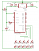
I have an electronic circuit, currently breadboarded that I am working on. Here is the schematic: **broken link removed**

The microcontroller should light LEDs in alteration, first one set, than another. However, all it does is turn on the first set of LEDs, unless I touch one of the wires on the breadboard. Then it starts acting as normal, until I let go, at which point it goes back to the first set of LEDs. It does not behave this way when I touch it with a pencil or another wire however.

What can I do to fix this?

Thanks,
Logan Williams
 
Ehhhh keep touching it???

But seriously, maybe that wire needs ground, which by touching it, you are. Or maybe you are creating resistance from the wire to another pin or whatever.... Get it to work, then replace you with a high value resistor. See what happens...
 
hi logan,

Its most likely an 'open', floating pin on the PIC. Its picking up hand capacitance or hand contact.

Check the datasheet and look for unconnected pins, which must not be left 'floating'.

Is this clear, if not just ask.

EDIT: is the drawing of complete circuit or are there 'bits' missing?
 
Last edited:
I have a micro on solderless breadboard, much like yours. Mines does the same thing from time to time. Try what Eric said, I bet thats the problem.
 
Nigel Goodwin said:
There shouldn't be any problems leaving PIC pins floating, UNLESS you are reading them, but why would you read an unused pin?.

I thought you were supposed to tie them either high or low with a high value resistor if they were unused. Or can you just set them as output and let them float?

I have the exact same problem with my setup, but mine is intermittant. It will work okay and then just stop, poke it a little and it goes again. It only happens when I run my board off a battery and not power it from my ICD2. I just figured it was static/capacitance and would go away if I tied the unused pins down and didn't have it on a solderless board.

Logan - is your circuit on solderless board as well?
 
Andy1845c said:
I thought you were supposed to tie them either high or low with a high value resistor if they were unused. Or can you just set them as output and let them float?

You're thinking of CMOS logic chips, with a PIC if you don't read the pin, and it's not triggering an interrupt or something, it can't upset circuit operation.

There was a long running thread on the PICList years ago, about should you set unused pins as inputs or outputs, the outcome was it didn't really seem to make any difference - and was mostly a matter of personal choice.

Personally I don't ever even think about it, just use the pins I want, and ignore the rest.
 
Personally I don't ever even think about it, just use the pins I want, and ignore the rest.

Works for me too.

I think the problems may be due the plastic breadboard. I have built circuits on these and noticed similar strange effects. Seems that the larger the board, the more troubles one can have. What seems to help is having an electrolytic cap where the power supply enters the board.
 
The strange thing is that it happens no matter what wire I touch. I already have caps at the power supply.

What is shown in the schematic is everything that I have connected.

It does the same thing even on a smaller breadboard.

I have not setup the unused pins as inputs or outputs, just ignored them. Should I TRIS them as inputs and ground them?
 
hi logan.
If you have programmed the PIC yourself, have you correctly configured the CONFIG bits ?.

I would try setting PORTB to all outputs, just to avoid any open inputs.

Can you post your coding along with the Config header.?

I often use a project board for 4MHz PIC's, if the sockets are clean and the jumpers are tinned, I don't get any problems.
 
Nigel Goodwin said:
Never use breadboards, don't have that problem! :D

But its so easy to change things with breadboard.....:p
 
hi,

> You don't need to change it if you design it right in the first place

The point I find most useful with the project/breadboard is that the components ie: resistors/caps etc, can be re-cycled many times.[ its eco!] and its a lot cheaper for the hobby/projecteer.

It also cuts down on the assembly time.
I don't think its sometimes a question of design at the 'what if' stage of a project.

Often most of us just build a breadboard lashup just to try an idea or to test a component or a small part of a main project.
 
Nigel Goodwin said:
You don't need to change it if you design it right in the first place :D

lol, i'm not quite to the point where I can design anything with a PIC. Heck, I spent an hour lastnight making one turn an LED on and off with a switch:eek:

ericgibbs said:
The point I find most useful with the project/breadboard is that the components ie: resistors/caps etc, can be re-cycled many times.[ its eco!] and its a lot cheaper for the hobby/projecteer.

I like that fact too. It gets hard to push those 1/4 watt resistors in after the leads get all bent up though!
 
Last edited:
I already have caps at the power supply.

What is shown in the schematic is everything that I have connected.

C1 is doing nothing, you can remove this, or move it to the input side of your regulator. What I don't see is small bypass caps - 0.1 uF both near the pic Vdd and Vss connections, and between the regulator and C2. This could be the reason...

I would also take Eric's suggestion about setting your portB to outputs.
 
What do you mean by two small bypass caps? Where between the regulator and C2?

Thank you everyone for your help so far!
 
What do you mean by two small bypass caps?
small ceramic capacitors, for example mono 104s

Where between the regulator and C2?
From Vo to ground, but before C2.

I'm going to try and find a photo I can link to, to show you the type to use. It may take a while...
Hard to find a clear photo, but if you look on this page at the second photo down:
https://www.phanderson.com/picaxe/
between the regulator and the smaller electrolytic, you will see one. I don't see a bypass on his stamp, though.

The first place I looked was Nigel's tutorial, but it seems he uses a 1 uF electrolytic? (If Nigel does it, it'll work!) :)
 
Last edited:
hi logan.

I'll ask the questions again.

If you have programmed the PIC yourself, have you correctly configured the CONFIG bits ?.

I would try setting PORTB to all outputs, just to avoid any open inputs.

Can you post your coding along with the Config header.?

Like to help.
 
Okay, I have modified the schematic and circuit to that that is attached. However, it still does not function as it should, and I am having the same problem that I had before.

Here is my code (I will try setting PORTB outputs soon). Sorry for the sloppiness, but this is just test code to make sure that the circuit is functioning correctly.

Code:
		list	p=16f88
		radix	hex

status	equ		0x03
porta	equ		0x05
ncount	equ		0x21
mcount	equ		0x22
osccon	equ		0x8f

rp0		equ		5

		org		0x00

start	bsf		status,rp0	;bank 1
		movlw	b'01011110'	;8Mhz internal clock
		movwf	osccon
		bcf		status,rp0	;bank 0

		movlw	0x00
		tris	porta
loop	movlw	b'00010101'
		movwf	porta
		movlw	0xFF	;prepare a 0x40 pause
		call	pause		;longer pause
		movlw	b'00001010'
		movwf	porta
		movlw	0xFF	;prepare a 0x40 pause
		call	pause		;longer pause
		goto	loop

pause	movwf	mcount		;move set W to mcount
loadn	movlw	0xff		;load n with FF
		movwf	ncount		;load ncount with W
decn	decfsz	ncount,f	;decrement ncount
		goto	decn		;if ncount is not 0 go back to decn
		decfsz	mcount,f	;decrement mcount
		goto	loadn		;if mcount is not 0 go back to loadn
								;	this restarts n with a fresh val
		return
		end

Thank you!
 

Attachments

  • povclock01.png
    povclock01.png
    11.8 KB · Views: 158
Status
Not open for further replies.

New Articles From Microcontroller Tips

Back
Top