Continue to Site

Welcome to our site!

Electro Tech is an online community (with over 170,000 members) who enjoy talking about and building electronic circuits, projects and gadgets. To participate you need to register. Registration is free. Click here to register now.

  • Welcome to our site! Electro Tech is an online community (with over 170,000 members) who enjoy talking about and building electronic circuits, projects and gadgets. To participate you need to register. Registration is free. Click here to register now.

Help with audio amp design

Status
Not open for further replies.

hellohello

New Member
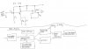
I am designing 1W Audio Amplifier with mute and volume control which allow end-user to select two different types of frequency response, namely speech and music.The selected choice must be indicated using LEDs (three) which is the end-user has a choice of selecting voice (300hz to 3.3K hz), music or mute mode.

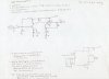
I am a noob in this kind of subject and am now learning. I have come up with the pre amp circuit but wasnt sure how to combine the transistor switching circuit (using SPDT switch- simulated 2 bit signal for mode selection) to the pre amp before connecting to audio amp and speaker (I am using TDA7052A audio amp and 0.5W 8 ohm speaker)

Attached is the draft I have come up with, the left is the pre amp and the right is the circuit for audio amp which I hope both are correct. I left out the transistor switching circuit (require 5V)(suppose to connect to pre amp) as i am not sure how to proceed.

I have left out the calculations as I am still trying to figure out how to calculate as I need the complete diagram first.


Really need your help here . :confused:

I have searched through the net and threads but hasnt found anything similar. :confused:


Urgent help appreciated!:)
 

Attachments

  • draft.jpg
    draft.jpg
    96.5 KB · Views: 665
I can't see your pastel on grey schematic photo and I can't read your writing.
Why not sketch the schematic clearly using Microsoft Paint program or something and type your text?

If you use a modern low noise opamp in your preamp then the transistor is not needed.
Is the input a microphone?

Why do you want to cut off the very important consonants sounds of speech that extend up to 14kHz? Why cut off the fundamental low frequencies of speech?
 
DC coupling the bjt to the op amp makes no sense, you're going to be amplifying the DC component as well, probably railing the op amp's output. There is no point in having the bjt in front of the op amp anyway.

Use an LM386 to do what you want. There are tons of apps on it in the net as well as here. Filter to your discretion, but it makes no sense to kill off some of the speech bandwidth.
 
DC coupling the bjt to the op amp makes no sense, you're going to be amplifying the DC component as well, probably railing the op amp's output.
No.
The opamp has a DC gain of only 1 because there is a capacitor in series with the feedback resistor to ground. So its DC output is the same as the voltage on the collector of the transistor.

Use an LM386 to do what you want.
The LM386 has a low output power and a huge output coupling capacitor because it is single-ended. The TDA7052A amp selected is bridged for almost 4 times the output power of an LM386 and it does not need an output coupling capacitor. I think a TDA2822M is better.
 
the conditions is already set so I can only use TDA7052A amp. And as for frq, I was told that the voice is from 300 hz to 3.3k hz and there isnt any need for music filter.

The components which I can use is UA741 (op amp), TDA7052A, LM78L08, transistor 2N3904, SPDT switch...l the rest are resistors are capacitors and LEDs.

Thats the components I have to use. It is actually my first mini project and I am quite lost as I just started learning this subject. I got to hand in my first draft by this friday.


I'm sorry about the bad image of my draft circuit. Attached is the new one...hopefully it is better by using paint.

The circuit for TDA7052A can be found here: (pg 8)
**broken link removed**


The block diagram has been included inside attachment so that there will be better understanding of what i am trying to do. Thanks for your help!
 

Attachments

  • draftpaint.jpg
    draftpaint.jpg
    62.3 KB · Views: 576
Status
Not open for further replies.

New Articles From Microcontroller Tips

Back
Top