Continue to Site

Welcome to our site!

Electro Tech is an online community (with over 170,000 members) who enjoy talking about and building electronic circuits, projects and gadgets. To participate you need to register. Registration is free. Click here to register now.

  • Welcome to our site! Electro Tech is an online community (with over 170,000 members) who enjoy talking about and building electronic circuits, projects and gadgets. To participate you need to register. Registration is free. Click here to register now.

Help with alarm clock / comparator circuit

Status
Not open for further replies.

elec_newb

New Member
I have an alarm clock which I am trying have beep a horn instead of the built in speaker. I have soldered some points to the alarm clock so that when the horn should go "beep" it outputs 1.5V, and when it should be off or intermittent, it is outputting 5V.

The device to make the sound draws 6A@12V, so I need to run it off a relay... but the voltages given out by the alarm clock are insufficient to trip the relays I have, and I haven't found one online that could provide a dropout voltage of ~1.5V.

My first thought was to research some type of thresholding device, so that 0V meant blow the horn, and 5V meant shut it off. I went to Radio Shack and bought an LM339N comparator. With access to the datasheet, I still can't figure out how I'm supposed to get it to work... even at an elementary level.

Quick pinout: http://circuits.datasheetdir.com/177/LM339-pinout.jpg
Here is the datasheet: **broken link removed**

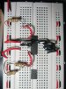
Pin 1: is connected to a resistor, and that resistor to the negative of a 9V battery
Pin 2,13-14: NC
Pin 3: positive of 9V battery
Pin 4-5,8-12: negative of 9V battery
Pin 6: details below
Pin 7: details below

I've tried putting 6 to positive and 7 disconnected, 7 to positive and 6 disconnected, I've even tried connecting the positive of a AA battery to it (when doing so I connected the neg on the 9V and the neg on the AA, is that okay?). I do not get any output out of Pin 1, regardless of the configuration.

Could someone help me out? Thanks!
 
Delayed a bit in the moderation queue... anybody able to help?

hi,
When using a LM339 as a comparator for the 1.5V and 5V signals you have to give the LM339 a reference voltage some where between the two limits.
Say about 3Vref, so when the output from the alarm is 1.5V the LM339 output is low and when the alarm output is 5V the LM339 output is high.

You will require a medium power transistor between the LM339 output and the relay coil. [transistor type like a 2N2222]

Do you follow OK.?
 
Last edited:
hi,
A circuit of this type would be ok for the project.
 

Attachments

  • AlarmBeep1.gif
    AlarmBeep1.gif
    27.2 KB · Views: 253
Thanks so much for the circuit diagram Eric, you rock!

I have been focusing on just the comparator trying to get to that to work. My frustration has lead me to take a picture and hope you'll take a look at it. I've built a 25% voltage divider with some resistors (470ohm and 150ohm) I bought earlier and connected it to V+. 8V is coming out of my 9V battery, and is connected directly to V- and Vcc. Shouldn't I be getting 8V out of the output (since V+ < V-)? I'm getting 0V... swap V+ and V-, still 0V... Tomorrow I'll go to radio shack and pick up some larger resistors (maybe I'm giving it too many amps).

Per the diagram... I read before that the diode is to prevent the blowback from the coil when it disconnects. What is the 2N2222 transistor for?

At the risk of embarassing myself, maybe I'll upload the circuit I had drawn out before :)
 

Attachments

  • Breadboard2.jpg
    Breadboard2.jpg
    111.2 KB · Views: 273
Thanks so much for the circuit diagram Eric, you rock!

I have been focusing on just the comparator trying to get to that to work. My frustration has lead me to take a picture and hope you'll take a look at it. I've built a 25% voltage divider with some resistors (470ohm and 150ohm) I bought earlier and connected it to V+. 8V is coming out of my 9V battery, and is connected directly to V- and Vcc. Shouldn't I be getting 8V out of the output (since V+ < V-)? I'm getting 0V... swap V+ and V-, still 0V... Tomorrow I'll go to radio shack and pick up some larger resistors (maybe I'm giving it too many amps).

Per the diagram... I read before that the diode is to prevent the blowback from the coil when it disconnects. What is the 2N2222 transistor for?

At the risk of embarassing myself, maybe I'll upload the circuit I had drawn out before :)

hi,
Upload your circuit diagram so that we can check your connections.
 
I beautified my circuit so it is fit to read... whether or not it actually makes sense is another matter. If it would not work, I would be grateful to learn why.
 

Attachments

  • Circuit.jpg
    Circuit.jpg
    45.8 KB · Views: 298
The complete circuit I just posted was not meant to be what I showed in the breadboard... I just happened to post it a minute afterwards... Sorry about that. I'll show what I was trying to do on my breadboard in a couple minutes.
 
Here is the small circuit that I tried implementing on my breadboard. When I measured voltages, I always read 0V.

hi,
You will always read 0V.!

The LM339 is an open collector output, add a 2K2 from the output pin to +Vsupply.

Look at this image of the LM339 cct.
 

Attachments

  • AAesp01.gif
    AAesp01.gif
    10.8 KB · Views: 277
Just a few moments ago I got the horn sounding off of the alarm clock. Thank you very much! I am still confused a bit about what an "open collector" is exactly and how it works (even after going to wikipedia)... I'm seeing that this output pin acts almost as if it's a ground when it is "on" and it acts as an open circuit when it is off... is that a good way to think of it?
 
Just a few moments ago I got the horn sounding off of the alarm clock. Thank you very much! I am still confused a bit about what an "open collector" is exactly and how it works (even after going to wikipedia)... I'm seeing that this output pin acts almost as if it's a ground when it is "on" and it acts as an open circuit when it is off... is that a good way to think of it?

hi,
Thats a fair way to think of an o/c output.
Its basically a switch,
when the switch is ON [transistor conducting] the external load resistor is connected to 0V, current flows from the power supply thru the external load resistor.
When its OFF [transistor not conducting] the external load is disconnected from 0V , so no current flows in the external load resistor.
 
Hi,

I'm doing a project where we have to have an electric circuit diagram on a current electrical device which has improved the lives of people.
I've chosen an alarm clock,
i have had a look at some of the circuit diagrams you have posted and am a bit stumped as to what things are.
Would any of you possibly be able to post an explanation of the circuit so i know what i'm talking about to my science teacher.
some particular things that have stumped me are some of the numbers that you have labelled with the resistors, what are they? are they measurements of resistance in ohms?
Also what are the Triangles?

Cheers,
Sick_Kent

hi,
Which post number are you referring too for the circuit.???
 
Post #7 seemed to be the one I understood clearest yet i am still a bit hazy with the details

hi,
Added some comments on that circuit.
 

Attachments

  • Circuit.jpg
    Circuit.jpg
    46.7 KB · Views: 154
In the circuit shown the diode is in series with the relay coil. That won't work. The diode, for spike suppression, should be in parallel with the relay coil with its cathode connected to the positive supply. Also, a transistor buffer stage (the 2N2222) should be between the comparator output and the relay coil.
 
Last edited:
In the circuit shown the diode is in series with the relay coil. That won't work. The diode, for spike suppression, should be in parallel with the relay coil with its cathode connected to the positive supply.

The OPA going high drives the coil via the diode, the low side of the coil is connected to 0V, so it will work if the OPA is able supply the required V and I,,, a diode across the coil is also required.
 
Agreed. But if the diode as shown isn't for spike suppression what is it for? It seems redundant.
Further, the comparator shown in the sketch is wired with the wrong polarity; its output goes high when the alarm input goes above 3V.
 
Status
Not open for further replies.

New Articles From Microcontroller Tips

Back
Top