Continue to Site

Welcome to our site!

Electro Tech is an online community (with over 170,000 members) who enjoy talking about and building electronic circuits, projects and gadgets. To participate you need to register. Registration is free. Click here to register now.

  • Welcome to our site! Electro Tech is an online community (with over 170,000 members) who enjoy talking about and building electronic circuits, projects and gadgets. To participate you need to register. Registration is free. Click here to register now.

Help with a Sequential Logic circuit

Status
Not open for further replies.

dpresley58

New Member
Hi,
I'm trying to build a switching circuit. It will sequentially select between one of 3 audio inputs. Is there a cookbook approach to this, or possibly a chip that already implements this?

Thanks in advance.
 
there are audio switching ICs like 4066 etc, that can be used to select from many inputs and give only one out put. what you need to do is to make another circuit to sequentially make the control input of the IC to go high. there are many ways to do that.
 
Thanks for the response. Can you point me in the right direction for the other portion of the circuit? For some reason, I'm having trouble seeing how all this goes together.
 
We need a little more about the project.
Do you push a button to go to the next sequence?- turn a knob? - or do you want it to go "round and around" automatically? If so how fast?
 
The activation will be via a momentary footswitch. If you're familiar with guitar "stompboxes" (effects boxes at the feet of the player), that's what it'll be for. It has become more and more common for a single player to be a multi-instrumentalist. Instead of running three different signal cables to the mixer, this will reduce it to a single one. The individual instruments will be cabled to this box, into three different inputs. For example, the player picks up an acoustic guitar patched into channel 1, plays a song and then switches to mandolin in channel 2, and so on. At every instrument change, the player will need to hit the footswitch and cycle through the three channels to get to the one hooked to the instrument he is currently playing.
I hope this helps, and thanks for the reply. I've been making analog devices for guitars for some time now, but this is my first venture into digital logic. Frankly, I've yet to grasp some of the concepts. Mostly, I just want to avoid reinventing the wheel if there is a concise approach to this application already out there.
 
Audio Switch

I think this one will work. Lets see if someone will double check it because I didn't build or model it.

A little DC supply will power it.
 

Attachments

  • Audio Switch.PNG
    Audio Switch.PNG
    93.7 KB · Views: 622
I think this one will work. Lets see if someone will double check it because I didn't build or model it.

A little DC supply will power it.

sure it will work, R2,C2 & D1 can be eliminated, for reset without any delay. ie: pins 15 & 7 will be connected directly. input can be directly wired through 4066 without any resistor, better can have a check to know the difference when assemble.
 
No!

the CMOS switches have a resistance of some 100Ω.

Better use multilateral switches like MAX312 ... MAX314.

They have an On-resistance of 10Ω (and can stand higher currents), far below the well known 4016 or 4066.

They can be activated the same way.

Regards

Boncuk
 
Last edited:
I'm going to have to take some time to print this and mull it over. In the time since the last message, I've been studying digital logic and switching and came up with a schematic sketch on paper. Its gratifying to see my approach is similar to the one you posted. I -do- see how it works, though.

Mine uses a 555 timer to generate the Logic High pulse to clock a CD4017 with the outputs connected just as I'm seeing in your sketch. (I finally stumbled onto the concept of using the last output of the series to feed the reset... It was encouraging to see you using it, too. )

What I don't know yet is whether the reset for the 4017 sets all outputs low. I assumed it did. If this is the case, wouldn't I need an inverter on output Zero to flop it before it hits the actual switch?

For the switch, I found a CD4053, but will also pull the datasheets for the other devices mentioned. One of my main problems starting this idea was lack of familiarity with what devices are available, as well as the relative advantages/disadvantages of using them. I really appreciate way so many of you have offered your ideas here.

The power source for this will be a 9v battery or power supply. They're just the standard for guitar effects boxes. Will this change the component values you've shown here?

I've just now pulled the datasheets for the devices shown in your version and need to study them a bit. I'll also put what I came up with into a readable format and ask you guys to take a look at it.

Thanks to all for your continued participation, and your patience with a "digital newbie".
 
OK. A little explanation:
R1 C1 debounces the pedal in case it is not a clean pulse. Without it the counter might count several times with one pump.
R2 C2 power on reset to make sure it comes up on 0 and not 7 or 8.
1N914 is reset from + 3 count. C2 helps make sure this pulse lasts long enough to reset all the counts.
All of the dividers with the coupling caps are an attempt to have all the devices switch from the same DC voltage. This will help reduce the "pop" you sometimes hear when switching.
If the lower resistance switches have similar turn on voltages they would have less loss and be better. Don't know about price and availability.
You might want to add a little LED to the output of each count (If you can see the box) so you will know which is selected.
 
you asked about reset, when it resets it will imediately will give output to #1. (ie if the reset is not set with delay), so when out put#4 (connected to reset) goes high it will imediately (negligible delay in low freq) will turn on out put#1.
you can read the datasheet for further information
 
Last edited:
Is there a problem with using the 555 to clock the CD4017? (Just asking out of ignorance)
I've pulled the datasheets - still looking them over.

Ron, thanks for the circuit explanation. Its always helpful for me to have it laid out like that. I understand that biasing the inputs to around 1/2 the Vs is the way to go with regard to switch popping. The question arises, would there be a problem with establishing one central divider and hooking each input to it, or is the individual approach required?

If my research is correct, the LED indicators would need a transistor driver to buffer the CD4017's outputs due to CMOS's low ouput current. Is this right? Also, as an aside, I've also read (several times) that all unused CMOS inputs must be tied to a specific logic level.

I looked at the MAXIM line - they're sure proud of them. Mouser has them for about $11 USD each. Not sure I want to spend that much per pedal, although the idea of the 10 ohm input resistance is tempting. I'd really like to have this be as distortion free as possible. I ordered some samples to take a look.

Lastly, I mentioned in a previous post that these units would have a 9v supply. How would that affect the component values of your schematic?

I'm taking a closer look at this and see that you've implemented another divider at the output, along with what is probably a cap for decoupling the output into the next stage. Why is the additional divider there?

What I haven't mentioned until now is that the audio output of this switch will be fed into a buffer (essentially an audio line driver) and into a preamp. If that circuit has a cap on the input, is the one in your schem required?

Please understand I'm inquiring... not challenging. As mentioned before, its a learning curve for me.
 
A preamp is a good idea for analogue switches (4066, or 4051/2/3) since they have relatively high on resistance. But using them for audio there are a couple of issues. Firstly, the signal being switched has a limitation of the supply rails. The CD4053 series has a 'VEE' pin, which can go as low as -5V. This is to allow one to route analogue signals that go above and below ground (= audio). The CD4066 doesn't have this facility (as far as I know) so if powered by 9v, the input signal can only be between 0v and 9v.

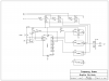
However, ronv has cleverly added bias resistors to the inputs. The input capacitor blocks any DC offset (so your input signal is centered around 0v, ground) and the two 47k resistors shift this so it is centred at half the supply voltage, 4.5V. Meaning your analogue signal will start to clip at around 4.4V - but most line audio is 1V peak to peak, and guitar signals generally stay below 3v p-p. The outputs are coupled with capacitors to remove this 4.5 offset, returning the signals to 0v centered. The one caveat with these bias resistors is the input impedance. with 47K resistors thats around 23k input impedance. Fine if it is being fed by a buffer, or 'audio out', but if it is straight from a guitar, you'll want a buffer on the input too, one with high impedance.

The second issue with logic analogue switches is the off resistance. As I'm sure you're planning on amplifying the outputs, any 'bleed' through of the signal could well be heard after amplification. Although the off resistance is measured in megaohms, and ron's schematic has bias resistors on the output, there still may be some bleed through in the output from unselected inputs. A quick way to sort this is to shunt the unselected inputs to ground with another 4066, or mosfets. This makes sure NO signal goes though the switch and couples to the output when it isnt' selected. It also prevents 'crosstalk' between analogues switches in the same package.

There are actually quite a few app notes about this subject, because, as you noticed, maxim like to plug their line of awesome analogue switches, and point out the flaws in existing designs. Whilst they are obviously promoting their product, they make some excellent points. - Doesn't mean to say we have to use maxims chips though!

All in all, using the analogue switches can be very useful, but certain precautions must be made for a 'clean' transparent routing of audio, which means a few extra circuits before and after the switches - especially for pre-processed signals, where any noise/distortion/crosstalk is bound to be amplified by later processes in the audio chain.

If you're a guitar pedal fan, you can check out schematics for the boss series of pedals. Their bypass switching uses JFET's, same principle as your idea, just with only two possible channels, works on 9v, is low power, and as its designed for 'guitar input', does very well to keep signals 'clean'.

I have had similar projects in the past, and have collected a fair bit of info on it (for analogue multieffects). So, even though I tihnk ronv has done a smashing job with that schem, simple but effective, if you have more questions, I'm all ears :D

Blueteeth
 
You could clock it with a 555, but it seems redundant.
Yes you would need some sort of buffer to drive the leds.
$11? And that's not for a dozen?
Always good practice to ground unused inputs. Nothing good happens with floaters.
I suppose you could use a common mid point voltage, but you would want it to be a very low impedance to avoid crosstalk.
Without knowing the input configuration of your amplifier it's hard to say if the output divider can be removed.
Good questions. I'm no expert on this stuff so we are both learning together.
 
Ron,
I figured out this morning why you put the "additional" divider on the output. Then, in reading Blueteeth's (BT's) explanation, I was able to have it confirmed. Of course the output would need it, just as much as the input would. Duh. Silly question on my part.

You guys bear with me - I'm going to outline the device in its entirety (which should have been done in the first place).

One musician on three different instruments. No more than one will be used at a time. The signals will be coming straight from the instruments and will not be subjected to preprocessing.

Based on BT's comment about it being a good idea to run these through a buffer, I got the idea this morning to run 'em through the normal buffers that I already have in the circuit, first. (They're using TL072 opamps, and are set up with input Z of about 2M) Then run them through the switches. That should handle the problem of overcoming the voltage divider issue. I've already done a 2-input version that runs through these buffers.

Okay, so now we have the signal coming in from the jacks, through the buffers (individual ones for each input), through the switches and on to a small preamp that gets used as a clean boost. It is very similar to the one here: AMZ Mosfet Booster Guitar Effect, and has an input Z of approx 10M.

Use of this booster is set up on another footswitch in an on/bypass configuration, and is optional. In other words, it won't be used all the time. For clarity's sake, the 3PDT footswitch diverts the signal completely around the boost when not used.

Regarding crosstalk: If only one of the three signal sources is being used at a time, is crosstalk that much of an issue? I can understand trying to squelch it as much as possible if three constantly active signals were vying for the output's attention, but this is a slightly different case, isn't it?

Regardless of whether the concern is necessary for this circuit or not, where can I get more information on reducing crosstalk with digital switches?

You guys really have me thinking. Thanks! This is great... :)
 
Last edited:
I think the crosstalk is due to the switches layout on the same die. So here is a thought for you. Use 3 separate 4066's and put the 4 in each package in parallel. This will also reduce the drop by 4X.
Be careful adding to much "stuff". Try to keep the unshielded wire lengths to a minimum or you will have some 60 HZ pickup much higher than the crosstalk.
Add a decoupling cap (say 10 ufd.) from the power supply to the dividers to ground.
Here is a site with some info on the impedance. I don't think you will need another amp, especially if you already have a preamp after the switch.
 
I am with Boncuk on this one, the CD4066 is obsolete and is a dooky part. Digi-key has a cost VS. performance compromise part, the DG412. The part cost $3.84 and has respectable specs.
Digi-Key - DG412DJ-E3-ND (Manufacturer - DG412DJ-E3)
Data sheet:
https://www.electro-tech-online.com/custompdfs/2010/11/dg411.pdf
Now crosstalk may or may not be an issue. You have to do the numbers to figure that one out. You need to look at your audio levels you are working with and gain distribution and also switch specs. The DG412 crosstalk is 85 dB down from adjacent channel, so say your audio in chan 1 switch is 224 mv then the crosstalk would be around 12uv which is probably into your noise floor and may be a non issue. Off isolation is another spec to look at, the DG412 off isolation is 68 dB. The part Boncuk mentioned has better isolation specs and lower on resistance but at a price.
 
Last edited:
My 'magic bullet' bookmark when I was working on something similar (almost identical, two guitars and a bass) was from a very clever guy on the diystompbox forum:

Bend Matrix 2 project

Although, perhaps over kill, he's done some good 'ol fashioned tinkering on getting the most out of analogue switches. Ergo: running two in series to double the 'off' resistance (bleed through), and shunting unused inputs. The 4066's are so cheap anyway, it won't break the bank to use many as ronv pointed out. Then you'll have 4 switches per channel to play with.

I should probably take this opportunity to do the same tinkering as my project went on hold because I'm lazy.

Thats a pretty clear description of what you're trying to do, something we don't often get on the boards :) And I agree that, if only one input (instrument) is kicking out a signal at any given time, then the other two shouldn't contribute anything audible on the output, but only experimenting will confirm that. Mains hum gets everywhere but I doubt it'll be loud enough to hear via bleed through - unless perhaps you're plugging this into a ridiculously high gain amp.

About other analogue switches. Its true, a better switch will make life a lot easier, and unless you're making many of these, will pay for itself. Isolation and crosstalk are the key parameters here, on resistance won't make much difference as you're using buffers on the inputs.

I should stop waffling, Ronv already mentioned most of what I was going to say lol
 
I ordered the components required for several options on this circuit. At this point, its probably best just to put it to the breadboard - the "throw it against the wall and see what sticks" approach. With any luck, there will be time to do that this weekend. I'm sure there will be questions next week - should be interesting.

Thanks for all the insight, and I'll be posting results soon.
 
Status
Not open for further replies.

Latest threads

New Articles From Microcontroller Tips

Back
Top