Continue to Site

Welcome to our site!

Electro Tech is an online community (with over 170,000 members) who enjoy talking about and building electronic circuits, projects and gadgets. To participate you need to register. Registration is free. Click here to register now.

  • Welcome to our site! Electro Tech is an online community (with over 170,000 members) who enjoy talking about and building electronic circuits, projects and gadgets. To participate you need to register. Registration is free. Click here to register now.

Help with a Oscillator circuit

Status
Not open for further replies.

furyfax

New Member
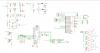
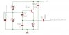
I'm using a HC49 crystal in a circuit, which is connected to an IC.
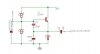
Just wundering is this is correctly designed and what the value of (pF,nF,mF etc) I should have on the output?
I've used **broken link removed** page as help for the design.

I guess this is just to block DC, so I'm thinking of using 10uF(micro), is this OK?
 

Attachments

  • HC49.pdf
    51.4 KB · Views: 229
  • skisse.JPG
    skisse.JPG
    12.9 KB · Views: 184
Last edited:
But mine will work OK ? I'm not a fan of analog-stuff (sorry), therefore I'm not so skilled in analog design.
 
Russlk said:
No, no, the cap goes to ground. That is the meaning of bypass. What you have is a coupling cap.
It gives new meaning to the term "DC blocking capacitor".:D
Of course, it would work if it were a zillion farads, and started out uncharged. :)
 
It has been my experience with this oscillator circuit that the output frequency will be lower than expected. This is because c27 and c29 are in series with each other but in parallel with the crystal, in this case 60pf which is far greater than the specified load capacitance. The ratio of those two capacitors also determines the feedback for osillations. The way around it is to put a small capacitor in series with the crystal, so the combined capacitance of the series capacitor and c27 and c29 = the load capacitance of the crystal.
 
Please post the schematic including the IC. It's possible that the IC doesn't require a separate oscillator, you can probab;y just add a couple of capacitors and a crystal and it will work.
 
Here's the whole schematic. It is not finnished at all. A lot of works remains.
The oschillator circuit is at the left, and is connected to pin 3 on the AD725.
 

Attachments

  • schematic.png
    schematic.png
    90.9 KB · Views: 203
Status
Not open for further replies.

Latest threads

New Articles From Microcontroller Tips

Back
Top