Continue to Site

Welcome to our site!

Electro Tech is an online community (with over 170,000 members) who enjoy talking about and building electronic circuits, projects and gadgets. To participate you need to register. Registration is free. Click here to register now.

  • Welcome to our site! Electro Tech is an online community (with over 170,000 members) who enjoy talking about and building electronic circuits, projects and gadgets. To participate you need to register. Registration is free. Click here to register now.

Help with a low power, power converter

Status
Not open for further replies.

rosspt

New Member
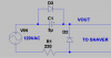
I'm looking for a schematic for a power converter to convert 110V to 220V for a 1.5W Chinese shaver. I know I could buy an adapter or converter online or travel store but what's the fun in that. I like doing little projects on my own. Things I've come across though (schematics) are large heavy transformers for high powered loads. I'm needing something small and light if possible. The device power input is 220V 50Hz 1.5W. Any help would be greatly appreciated.
 
hmm thats expensive! you're gonna need a new shaver! Inverters aren't cheap toys to make. I'd personally open it up and see if it hasnt been boarded to also be exported as a 220v model and see what components are needed for that. Alot of chinese products are mass produced, also intended for the 220/240v market and they all have similar PCB's with different component structures. Post a pic of the PCB (top and back)
 
pictures

hear are a couple pictures if it helps.
 

Attachments

  • IMG_0037.JPG
    IMG_0037.JPG
    3.7 MB · Views: 142
  • IMG_0038.JPG
    IMG_0038.JPG
    3.4 MB · Views: 156
Just by a small 5 - 20 VA 120/240 : whatever low voltage you want and put that in line with the power cord and use its two primary windings as a step down auto transformer to get the 120 volts the shaver needs.

Its the cheapest simplest way to get what you need at that low wattage level.
 
Not sure I understand

On the back it says it needs and input of 220V. Not 110V. It has an electric cord that plugs into a Chinese outlet, not a Canadian electrical outlet. So don't I need 220V not 120V to power it? Also not really wanting to buy batteries and solder them in and desolder every time they run out. Any other ideas? Also I'm really thankful by all the responses. I appreciate the advice and help.
 
As Bill stated, it might be a safer bet (not to mention simpler) just to use the AA battery.

It's quite possible that the thing will run off 110V directly.

That said, if you know what you're doing, and you want to make a converter, the cheapest, simplest & smallest I found would be a non-isolated converter IC - set it up for boost/buck-boost to give around 300V out ref: https://www.electro-tech-online.com/custompdfs/2011/01/60479.pdf .. There are other similar devices in a 3 pin package too but you'll have to look. The fact that the converter outputs a DC voltage shouldn't matter; the shaver appears to have a bridge rectfier on the input anyway. If you don't really know what you're doing, then I suggest you don't play with mains voltage.
 
What tcmtech is suggesting is to buy a small cheap 220 volt to 120 volt step down transformer and use it backwards. I think that is what he has in mind and should work. That or find a small 120 to 240 volt step up and use that. You aren't looking at any current to speak of and the first suggestion (240 to 120 backwards) should work fine. There is also the simply replace batteries which would work.

Ron
 
Last edited:
Thats what I meant but I just typed it back wards. I said step down when I should have said step up.
 
Another option would be to make a simple voltage booster circuit with a few diodes and capacitors. Being its such a low power demand that would not take much to make and would fit inside the shaver.
 
Another option would be to make a simple voltage booster circuit with a few diodes and capacitors. Being its such a low power demand that would not take much to make and would fit inside the shaver.
You'd need at least a 3uF 110VAC cap - which could be hard to find in small sizes (then again, maybe not).
 
Last edited:
Ok tcmtech, that's probably the best bet. I wrote it off in my head as all the mains (240VAC) rated caps I have seen are huge. As this is just 120VAC, it's not so bad... Also, with the use of an extra diode, the converter capacitor can be a polarised type (& therefore smaller yet again).

So rosspt, what do you think of the attached cct? The capacitor should be an electrolytic, 200VDC, >=3uF, minimum ripple current 75mA. Diodes can be e.g. 1n4004 or 1n4007, resistor can be 1/4W or higher.
 

Attachments

  • doubler.png
    doubler.png
    7.1 KB · Views: 142
Given that he only needs two or three watts at 240 volts the capacitor probably wouldn't need to be much over 2 uf if even that. As far as small 150 -250 volt AC rated capacitors go I have many small mylar and poly caps that are under 1.25" long by 3/4" high by 3/8" thick so I would think that one of those and a pair of 1 amp 400 volt diodes would be able to be retrofitted into the original shavers case without problems.

Also being a tiny SMPS I doubt it will be all that fussy about the input voltage if it is a bit on the low side. I have found many SMPS's are fairly forgiving to input under voltage conditions at light loads.

Something does not look right about your voltage doubler circuit you have. The one diode should be in series with the output not parallel to the capacitor. Plus being it dumps directly into a largish electrolytic capacitor I doubt the snubber resistor would even be necessary.
 
Last edited:
Given that he only needs two or three watts at 240 volts the capacitor probably wouldn't need to be much over 2 uf if even that.
110VAC^2*3uF*50Hz ~= 1.8W. 3uF gives about 300VDC @ 5mA (1.5W). Reducing the cap reduces the voltage.

I have many small mylar and poly caps that are under 1.25" long by 3/4" high by 3/8" thick
Sure. I haven't seen any around. I was [naively] thinking of caps a la fluoro ballast PFC caps (yes, ridiculous I know).

Also being a tiny SMPS I doubt it will be all that fussy about the input voltage if it is a bit on the low side. I have found many SMPS's are fairly forgiving to input under voltage conditions at light loads.
I also agree that it would probably fine connected directly.

Something does not look right about your voltage doubler circuit you have. The one diode should be in series with the output not parallel to the capacitor. Plus being it dumps directly into a largish electrolytic capacitor I doubt the snubber resistor would even be necessary.
It's irregular as the diode across the cap is to prevent it charging up backwards when initially connected or if the output voltage is ever < input instantaneous voltage; in any other condition is has no effect & allows the circuit to function as you would expect.

The resistor is to reduce the charge current into the 3uF cap, although it could rather be placed in series with D2, as the shaver circuit already has a series current limiting resistor. You are right that it could potentially be removed - although it does reduce stresses on the cap.
 
Last edited:
Why not just convert the thing to 110VAC input. by changing parts. Andy
 
Status
Not open for further replies.

New Articles From Microcontroller Tips

Back
Top