Continue to Site

Welcome to our site!

Electro Tech is an online community (with over 170,000 members) who enjoy talking about and building electronic circuits, projects and gadgets. To participate you need to register. Registration is free. Click here to register now.

  • Welcome to our site! Electro Tech is an online community (with over 170,000 members) who enjoy talking about and building electronic circuits, projects and gadgets. To participate you need to register. Registration is free. Click here to register now.

Help with a circuit

Status
Not open for further replies.

skeeterb

Member
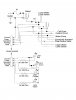
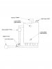
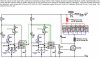
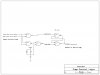
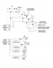
I need help getting a circuit finished. I have part of the circuit straight, but have been having trouble getting the pump and warning portion straight. I have decided to go to using an IC chip to control the switching of the circuit. What IC would be reccommended for the purposes of my circuit. I have included the circuit as it stands right now. I'm still kinda new to working with electronic circuits, but I am slowly learning what I need to know as I go along. If anyone can help me, reply here, or send me an Instant message here or on on of my IM Clients.
 

Attachments

  • Circuit 001.jpg
    Circuit 001.jpg
    345.9 KB · Views: 374
Last edited:
Before we can help, we are going to need more information. Here are some questions for you to answer:

- There appear to be two terminals to the left of F1. What do these connect to?
- the connectors that are labelled with "ground, power, operation, warn and refill", do these plug together?
- what is the purpose of Relay1?
- what is the purpose of this device? Please explain how it is intended to function.
 
Last edited:
Those two terminals to the left of F1 is the 12VDC input, i know i should have put that on the drawing but i neglected to put that in, sorry. Relay1 is part of the power circuit that turns on the whole thing. Its kind of a safety feature in case the switch S1 goes out in the ON position. I'm still working on putting more safety features on it to keep it stable in case something goes wrong. The circuit controls the Hydrogen on Demand Cell. It turns on the pump and actuates a control valve when the water level gets below the lower sensor and turns on a warning light that tells me the water level gets below the upper sensor. Yes, those two connectors do connect together. I drew them separate to keep my mind straight on the main part of the circuit. When the both sensors are holding the two portions of the circuit closed, it sends power out to the pulse control circuit which pulses the power going into the cell. The Hydrogen On Demand system is based on the ideas of Stan Meyer using pulsed power for electrolysis instead brute force electrolysis by direct power into the cell. After thinking about working with relays, I changed my mind and decided instead to use ICs for switching in my circuit. What IC chip is reccommended for what I want my circuit to do?
 

Attachments

  • CircuitChanged 001.jpg
    CircuitChanged 001.jpg
    372.5 KB · Views: 323
  • HydroxyCell 001.jpg
    HydroxyCell 001.jpg
    191.2 KB · Views: 233
Last edited:
Thanks for the update. I think I've got it mostly clear, except the pulse circuit. This schematic shows power going out to a cell pulse control circuit which is a separate item, right? So this will apply power steadily, and the pulse control circuit will look after pulsing the cell. is that right?

If you are not going to use relay's then this comment won't apply, but for the sake of my understanding anyway, please comment on this point...the way you show Relay1 doesn't make sense to me. If it is wired this way, the relay does nothing. Well, it switches on when the DC is applied, and it switches off when the DC is removed, but so what. If you remove Relay1 and just wire from F1 to S1 you get exactly the same operation. You say that it is a safety feature, but in fact it provides no safety at all as far as I can tell.

Similarly, I don't see the point of the second relay. If the Lower Water Level Sensor allows 12VDC to pass through to the relay, it will close, and 12VDC will flow through its contacts to the Cell Pulse Control Circuit. You would get exactly the same functionality if you simply remove the relay and wire from the Sensor to the Control Circuit. I can see one purpose for this relay, that is to "amplify" the current passing capability of the Lower Water Level Sensor so that enough current can flow to the Cell Pulse Control Circuit. But I suspect this isn't necessary. You can help determine this by providing a circuit or power requirement info for the Cell Pulse Control Circuit.

You have sprinkled rectifiers all over the place. I don't see why. For example, the rectifier near the coil of Relay1 is not necessary if you hook up the 12VDC the right way round. If you hook up the 12VDC the wrong way around, this rectifier prevents current flowing through the relay coil, but it doesn't prevent current flowing to other parts like to S1. It would be simpler to put one single rectifier in series with F1 to prevent all problems with reverse DC hookups. If you do this, you don't need the rectifier at the second relay, you don't need the rectifier on the Pulse Control Circuit ground return, you don't need the rectifier on the FLow Control Valve return and you don't need any of the rectifiers at either of the two connectors. You also don't need the rectifiers at the LEDs since the LEDs are in fact rectifiers.


Now, to get on to your interest in using an IC instead of the relays. It will probably be necessary to have some sort of relay or IC switch driving the water pump and control valve, but we need to know how much power they need. Please provide this info. One kind of switch that will work well is a high side switch, for example this one:
https://www.electro-tech-online.com/custompdfs/2007/07/FDC6330L.pdf
or a solid state DC switch, like this one:
https://www.electro-tech-online.com/custompdfs/2007/07/G3CN.pdf

I am interested to know what the circuit is connected to the Lower Water Level Sensor and the Upper Water Level Sensor. Can you describe these?
 
Last edited:
Relay1 is controlled by the key switch and S1 is the main power switch to the circuit. Those symbols i meant to be Blocking Diodes. They keep the power flowing in one direction and keep the other portions of the circuit from receiving power when it is not required. Looking again at the drawing, I do notice that I have a few too many blocking diodes. I will remove them in the next iteration of my drawing. The upper water level sensor is just part of the warning system telling the operator that the cell is low on water and will refill soon. The lower water level sensor is what actually runs the pump and pulse circuit. I have attached a circuit drawing that I have downloaded off of https://www.overunity.com. It is the heart of my Hydrogen on Demand system. I've been having trouble with trying to figure out how to keep the pump running until the water level returns to the level of the upper water level sensor.The way I have it currently drawn out, as soon as the water level gets to the level of the lower water level sensor, the pump will shut off and the water level will begin declining until the pump activates again. That has been giving me fits for about 2 weeks since I came up with this idea. I want it to turn off the pump ONLY after it reaches the upper water level sensor where it will turn the LEDS for refilling and warning off and return the cell to operation. I plan to use 2 cells so I will be building 2 circuits, one for each cell. All I am asking for is help to figure out that problem, so I can squash that pesky bug.
 

Attachments

  • ImprovedDD14Circuit.jpg
    ImprovedDD14Circuit.jpg
    82 KB · Views: 253
To run the pump you need a bit of logic. Its pretty simple. You have to feed the output of the LWLS and the output of the UWLS to two two-input gates. One of these gates is a NOR gate and the other is an AND gate. The output of the NOR gate becomes the pump START, and the output of the AND gate becomes the pump STOP. Now you feed the START into the SET input of an RS LATCH and you feed the STOP into the RESET input of an RS LATCH. The Q output of the RS LATCH becomes the Pump Enable line which is used to drive a switch or relay to run the pump. That's it. Well, there are some other bits to watch out for. On first application of DC power, you have to insure that the RS latch resets, so a bit of diode logic is needed coupled into the RESET input is needed. You also have to reduce the voltage of the logic inputs to the level tolerable by the logic family you choose. I recommend 4000 CMOS logic for the circuit as they have a wide voltage range and are inexpensive.

If this is confusing, let me know and I'll prepare a simple schematic.
 
Last edited:
Thanks RadioRon for the help, a simple schematic would help me a lot. I will complete the rest of the circuit, all I need is help getting that portion of the circuit working.
 
skeeterb said:
Thanks RadioRon for the help, a simple schematic would help me a lot. I will complete the rest of the circuit, all I need is help getting that portion of the circuit working.


Here is a logic diagram of the means by which you can control the pump. In this configuration, the pump will begin to run when the water is below the low level sensor, and it will continue to run until the water touches the upper level sensor, then it will shut off and stay off until the water again drops below the low level sensor.

This is a bare bones logic diagram, not a complete schematic. It is essential that this circuit be powered from a regulated DC power supply, which requires that you choose a suitable voltage (which depends on the electronic parts you choose), and then include a 78xx voltage regulator IC, where the xx is your voltage, and then wire the output of this regulator to the logic ICs that you use.

The inputs and outputs are Active High, or in other words, positive logic. This is not the only way to do this and may not be the most convenient. It assumes that your water level sensors put out a high voltage when they sense water and a low voltage otherwise. It also assumes that the sensor high voltage is within the input voltage range of the ICs that you choose. The output is active high but you will need a high current switch to power the pump and valve. I have not shown this high current switch.

Here is some theory of operation. G1's output will only go high when both of the inputs are low (i.e both sensors are "dry"). This is our signal to start the pump, so we call this "pump start". G2's output will only go high when both sensors are "wet" so we call this "pump stop". G4 and G5 are configured as an RS latch which is a two state circuit that will remember the last instruction given to it (hence the name "latch"). When it gets a high on "pump start" then the output "to water pump switch" will go high. When it gets a high on "pump stop" then the output will go low. Nothing happens when an input high to this latch goes low again, that is, the latch remembers that there was an input high before. The resistor/diode/capacitor circuit on G3 input generates a short pulse on "pump stop" when you first turn the power on, to insure the latch powers up in the right state under all conditions.

If you need additional assistance, post again.

RR
 

Attachments

  • student circuit.JPG
    student circuit.JPG
    121.6 KB · Views: 251
Last edited:
Power Circuit Help

Thanks ron. I was looking at different CMOS ICS and I know you would recommend 4000 Series CMOS IC chip. What 4000 Series CMOS chip would you use since there are more than more than one CMOS chip in that series?
 
Flow-through water cell

My cell will only use a pressure feed of water controlled initially by a ball valve. If I get more sophisticated, I will add an electronic control valve. The important point is that the cell is cooled by new water, and throttled by water. An off the shelf pump should do the trick if mounted in the water tank.
 
skeeterb said:
Thanks ron. I was looking at different CMOS ICS and I know you would recommend 4000 Series CMOS IC chip. What 4000 Series CMOS chip would you use since there are more than more than one CMOS chip in that series?


In fact I recommend the use of two chips here. One is a quad 2 input NAND gate IC, the most obvious choice being the 4011, but in fact you might be better off using the 4093 as this schmitt trigger type behaves better with analog inputs like our RC circuit. The other IC is a quad 2 input NOR gate IC, the most obvious choice being the 4001.

Both of these ICs have 4 gates in them, and you won't be using all 4 gates in each chip. It is absolutley essential that the gates that are not used have their inputs tied to either Vcc or ground, ground being typically more convenient. Don't forget this.
 
Thanks a lot man, you've really been helping me out with my IC logic search. One last thing, on the simple diagram what is capacitor and resistor in the input, I mean what is the resistance of the resistor and what is the capacitance of the capacitor that you have in the simple drawing? Could you draw the ICs as they would be put on the circuit instead of the simple drawing that you posted in an earlier post? I want to get that circuit finished drawing, so I can start testing the circuit before I start soldering the board together.
 
skeeterb said:
Thanks a lot man, you've really been helping me out with my IC logic search. One last thing, on the simple diagram what is capacitor and resistor in the input, I mean what is the resistance of the resistor and what is the capacitance of the capacitor that you have in the simple drawing? Could you draw the ICs as they would be put on the circuit instead of the simple drawing that you posted in an earlier post? I want to get that circuit finished drawing, so I can start testing the circuit before I start soldering the board together.


OK, will do but I would like to understand the circuit a bit better as well. I would like to know what the exact circuit is for the two water level sensors. Can you provide that info?
 
Circuit Description

RadioRon said:
OK, will do but I would like to understand the circuit a bit better as well. I would like to know what the exact circuit is for the two water level sensors. Can you provide that info?

The circuit simply turns the pump on and off when the water level falls below the lower sensor and rises above the upper sensor. When the water level falls to just below the upper sensor it turns on a LED indicating that the water level is about to fall below the top of the electrode stack of the Hydrogen production cell. The lower sensor turns off the pulse circuit, turns on the pump, actuates a flow control valve (to open), and turns on an LED that indicates the cell is refilling. when the water level reaches the upper sensor again, it turns the 2 LEDS (Refill, Warn), it closes the valve and returns the cell to operation. The circuit was inspired when I was at work and saw some relays that they take off of buses when they replace a crossing gate. It blossomed from there to the circuit that I posted with portions missing. That's why I've been so determined to get that information.
 
You misunderstood my question. I want details of the water level sensor. On your schematic, you show two wires that, presumably, connect to something. What do they connect to, exactly?
 
Water Level Sensors

I'm still working on that. I haven't decided what to use for my water level sensors yet. I may ask for some help on suggesting what to use for my sensors on the other site I visit frequently, https://www.overunity.com
 
I wouldn't even visit that place, it looks like they're all on drugs!
 
Hero999 said:
I wouldn't even visit that place, it looks like they're all on drugs!

Some people can be so skeptical. Dreamers like us (members of sites like overunity.com and others), are seen as crazy or on drugs when skeptics look at our wild ideas.
 
skeeterb, one of my favorite definitions for 'insanity' is "Doing the same thing over and over again expecting different results"
Different methods of attacking the 'problem' of over unity do not qualify as 'different things' as the atempted result is the same. There is nothing wrong with wild ideas, but 'dreamers' are people that work at univsersities in pure research positions, or similar.
 
Some of the most relevant inventions have come from people like me and others like me, dreamers. I can't name any right offhand, but that is how technology has developed over the last millennium to the level that it is today. If it wasn't for dreamers, the world would probably still be stuck in the bronze age. I don't like hypocrites, they annoy me to no end. Some of the new technology that is being developed today is being suppressed by big oil to keep the world dependent on petroleum. Just ask Stanley Meyers, oops too late he's dead, killed because of his water powered car and other hydrogen technologies will help put big oil out of business. I just came in here to ask for help to get a help with a circuit, but the last few posts have been hypocritical of the ideas that have been put on sites like overunity.com. People like radioron have been helpful and I have tried to help him understand how my circuit works, so he can help me develop the circuit that will control my Hydrogen on Demand system.
 
Last edited:
Status
Not open for further replies.

Latest threads

New Articles From Microcontroller Tips

Back
Top