I'm working on adding some custom interior lights to my car. I'm trying to achieve certain behavior and since I'm an aerospace engineer, I don't have a lot of circuit knowledge. The first circuit I whipped up ended up burning out my potentiometer. Oops.
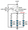
Let me describe what I'm trying to accomplish. My LEDs run on 12V. I have two circuits capable of outputting 12V: the parking light circuit and the dome light circuit. I would like the LEDs to be lit if either of these is on.
Here's the kicker: when only the parking lights are on, I want the LEDs to controlled by a potentiometer so I can vary their brightness. This is because the strips I have are too bright for ordinary night driving and need to be dimmed.
Then, when the doors are opened and the dome light circuit is on, I want the LEDs to see 12V. This will have the effect of increasing the brightness when the doors are opened, which would be awesome.
I've done the either-or case without the potentiometer with a pair of diodes. That works fine. But when I try adding in the potentiometer, it smokes.
I should also add that the voltage in either of these circuits is not a known constant. While the voltage in the parking light circuit is pretty close to 12V when they're on, the dome lights fade out and the voltage drops smoothly from around 12V to around 2V.
Can someone with more electrical engineering knowledge help me out a bit?
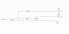
I attached a wiring diagram of my faulty, pot-smoking circuit for reference.
Let me describe what I'm trying to accomplish. My LEDs run on 12V. I have two circuits capable of outputting 12V: the parking light circuit and the dome light circuit. I would like the LEDs to be lit if either of these is on.
Here's the kicker: when only the parking lights are on, I want the LEDs to controlled by a potentiometer so I can vary their brightness. This is because the strips I have are too bright for ordinary night driving and need to be dimmed.
Then, when the doors are opened and the dome light circuit is on, I want the LEDs to see 12V. This will have the effect of increasing the brightness when the doors are opened, which would be awesome.
I've done the either-or case without the potentiometer with a pair of diodes. That works fine. But when I try adding in the potentiometer, it smokes.
I should also add that the voltage in either of these circuits is not a known constant. While the voltage in the parking light circuit is pretty close to 12V when they're on, the dome lights fade out and the voltage drops smoothly from around 12V to around 2V.
Can someone with more electrical engineering knowledge help me out a bit?
I attached a wiring diagram of my faulty, pot-smoking circuit for reference.