jawadlateef
New Member
Hi all
sorry to disturb you guys again.
please solve my little query regarding 89C51 and 8255 interfacing.
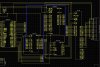
below is the code which i am using with the ckt attached.
1. plz tell me whether i need external pull up for port 0 of the controller for interfacing with 8255 and i think i dont need it for RAM 6264 as i saw in a book Scott MacKenzie's.
2. Is there any fault in the circuit you see plzz do mention it.
3. I want to drive LCD and later want to attach a keypad too. plzz help if you have any other code or suggestions.
i have tried alot but no result used the same LCD with other circuits and is fine but no result in this one.
Used 8255 as memory mapped IO even tried in assembly but no outcome.
Thanx alot in any event.
#include <REG52.H> /* special function register declarations */
/* for the intended 8051 derivative */
#include <intrins.h>
#include <stdio.h>
#include <string.h>
#define _8255_BASE_ADDR 0x8000
typedef unsigned char uchar_t;
typedef unsigned int uint_t;
uchar_t xdata _8255_mod _at_ _8255_BASE_ADDR + 0x3;
uchar_t xdata _8255_prt_a _at_ _8255_BASE_ADDR + 0x0;
uchar_t xdata _8255_prt_b _at_ _8255_BASE_ADDR + 0x1;
uchar_t xdata _8255_prt_c _at_ _8255_BASE_ADDR + 0x2;
void write_data_to_8255(uchar_t port, uchar_t *byte)
{
uchar_t control_reg = 0;
control_reg = _8255_mod;
switch (port) {
case 'A':
control_reg &= 0xEF;
_8255_mod = control_reg;
_8255_prt_a = *byte;
break;
case 'B':
control_reg &= 0xFD;
_8255_mod = control_reg;
_8255_prt_b = *byte;
break;
case 'C':
control_reg &= 0xF7;
_8255_mod = control_reg;
_8255_prt_c = *byte;
break;
}
}
void read_data_from_8255(uchar_t port, uchar_t *byte)
{
uchar_t control_reg = 0;
control_reg = _8255_mod;
switch (port) {
case 'A':
control_reg |= 0x10;
_8255_mod = control_reg;
*byte = _8255_prt_a;
break;
case 'B':
control_reg |= 0x02;
_8255_mod = control_reg;
*byte = _8255_prt_b;
break;
case 'C':
control_reg |= 0x09;
_8255_mod = control_reg;
*byte = _8255_prt_c;
break;
}
}
void set_mode_8255(uchar_t mode)
{
switch (mode) {
case 0:
_8255_mod = 0x80;
break;
/* FIXME: add code for handling below modes, not needed for now */
case 1:
case 2:
break;
}
}
void delay(uint_t t)
{
uint_t i, j;
for(i=0;i<t;i++)
for(j=0;j<10;j++)
_nop_ ();
}
void write_code_to_lcd(uchar_t cmd_code)
{
uchar_t byte;
byte = 0x80;
write_data_to_8255('C', &byte); //LCD_RW=0; LCD_RS=0; LCD_E=1;
byte = cmd_code;
write_data_to_8255('A', &byte);
delay(5);
byte = 0x00;
write_data_to_8255('C', &byte); //LCD_RW=0; LCD_RS=0; LCD_E=0;
delay(5);
}
void write_data_to_lcd(uchar_t disp_data)
{
uchar_t byte;
byte = 0xA0;
write_data_to_8255('C', &byte); //LCD_RW=0; LCD_RS=1; LCD_E=1;
byte = disp_data;
write_data_to_8255('A', &byte);
delay(5);
byte = 0x20;
write_data_to_8255('C', &byte); //LCD_RW=0; LCD_RS=0; LCD_E=0;
delay(5);
}
void display_data_on_lcd(uchar_t code *s)
{
while(*s > 0)
{
write_data_to_lcd(*s);
s++;
delay(50);
}
}
void lcd_init(void)
{
delay(2000);
write_code_to_lcd(0x38);
delay(50);
write_code_to_lcd(0x0c);
delay(50);
write_code_to_lcd(0x01);
delay(50);
write_code_to_lcd(0x06);
delay(50);
}
/*------------------------------------------------
The main C function. Program execution starts
here after stack initialization.
------------------------------------------------*/
void main (void)
{
uchar_t byte;
set_mode_8255(0);
byte = 0x15;
write_data_to_8255('C', &byte);
byte = 0x74;
write_data_to_8255('A', &byte);
byte = 0xf3;
write_data_to_8255('B', &byte);
// byte = 0x00;
// write_data_to_8255('C', &byte);
//
// lcd_init();
//
// write_code_to_lcd(0x84);
//
// display_data_on_lcd("Alhamdollilah");
//
// write_code_to_lcd(0xc1);
//
// display_data_on_lcd("Akhir chal pari");
while(1);
}
sorry to disturb you guys again.
please solve my little query regarding 89C51 and 8255 interfacing.
below is the code which i am using with the ckt attached.
1. plz tell me whether i need external pull up for port 0 of the controller for interfacing with 8255 and i think i dont need it for RAM 6264 as i saw in a book Scott MacKenzie's.
2. Is there any fault in the circuit you see plzz do mention it.
3. I want to drive LCD and later want to attach a keypad too. plzz help if you have any other code or suggestions.
i have tried alot but no result used the same LCD with other circuits and is fine but no result in this one.
Used 8255 as memory mapped IO even tried in assembly but no outcome.
Thanx alot in any event.
#include <REG52.H> /* special function register declarations */
/* for the intended 8051 derivative */
#include <intrins.h>
#include <stdio.h>
#include <string.h>
#define _8255_BASE_ADDR 0x8000
typedef unsigned char uchar_t;
typedef unsigned int uint_t;
uchar_t xdata _8255_mod _at_ _8255_BASE_ADDR + 0x3;
uchar_t xdata _8255_prt_a _at_ _8255_BASE_ADDR + 0x0;
uchar_t xdata _8255_prt_b _at_ _8255_BASE_ADDR + 0x1;
uchar_t xdata _8255_prt_c _at_ _8255_BASE_ADDR + 0x2;
void write_data_to_8255(uchar_t port, uchar_t *byte)
{
uchar_t control_reg = 0;
control_reg = _8255_mod;
switch (port) {
case 'A':
control_reg &= 0xEF;
_8255_mod = control_reg;
_8255_prt_a = *byte;
break;
case 'B':
control_reg &= 0xFD;
_8255_mod = control_reg;
_8255_prt_b = *byte;
break;
case 'C':
control_reg &= 0xF7;
_8255_mod = control_reg;
_8255_prt_c = *byte;
break;
}
}
void read_data_from_8255(uchar_t port, uchar_t *byte)
{
uchar_t control_reg = 0;
control_reg = _8255_mod;
switch (port) {
case 'A':
control_reg |= 0x10;
_8255_mod = control_reg;
*byte = _8255_prt_a;
break;
case 'B':
control_reg |= 0x02;
_8255_mod = control_reg;
*byte = _8255_prt_b;
break;
case 'C':
control_reg |= 0x09;
_8255_mod = control_reg;
*byte = _8255_prt_c;
break;
}
}
void set_mode_8255(uchar_t mode)
{
switch (mode) {
case 0:
_8255_mod = 0x80;
break;
/* FIXME: add code for handling below modes, not needed for now */
case 1:
case 2:
break;
}
}
void delay(uint_t t)
{
uint_t i, j;
for(i=0;i<t;i++)
for(j=0;j<10;j++)
_nop_ ();
}
void write_code_to_lcd(uchar_t cmd_code)
{
uchar_t byte;
byte = 0x80;
write_data_to_8255('C', &byte); //LCD_RW=0; LCD_RS=0; LCD_E=1;
byte = cmd_code;
write_data_to_8255('A', &byte);
delay(5);
byte = 0x00;
write_data_to_8255('C', &byte); //LCD_RW=0; LCD_RS=0; LCD_E=0;
delay(5);
}
void write_data_to_lcd(uchar_t disp_data)
{
uchar_t byte;
byte = 0xA0;
write_data_to_8255('C', &byte); //LCD_RW=0; LCD_RS=1; LCD_E=1;
byte = disp_data;
write_data_to_8255('A', &byte);
delay(5);
byte = 0x20;
write_data_to_8255('C', &byte); //LCD_RW=0; LCD_RS=0; LCD_E=0;
delay(5);
}
void display_data_on_lcd(uchar_t code *s)
{
while(*s > 0)
{
write_data_to_lcd(*s);
s++;
delay(50);
}
}
void lcd_init(void)
{
delay(2000);
write_code_to_lcd(0x38);
delay(50);
write_code_to_lcd(0x0c);
delay(50);
write_code_to_lcd(0x01);
delay(50);
write_code_to_lcd(0x06);
delay(50);
}
/*------------------------------------------------
The main C function. Program execution starts
here after stack initialization.
------------------------------------------------*/
void main (void)
{
uchar_t byte;
set_mode_8255(0);
byte = 0x15;
write_data_to_8255('C', &byte);
byte = 0x74;
write_data_to_8255('A', &byte);
byte = 0xf3;
write_data_to_8255('B', &byte);
// byte = 0x00;
// write_data_to_8255('C', &byte);
//
// lcd_init();
//
// write_code_to_lcd(0x84);
//
// display_data_on_lcd("Alhamdollilah");
//
// write_code_to_lcd(0xc1);
//
// display_data_on_lcd("Akhir chal pari");
while(1);
}
")
